
Users Manual

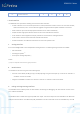
Table Of Contents

SGW101X Series
@2019 | SG Wireless Limited
Confidential Proprietary
Website : www.sgwireless.com
7
B. RF antenna interface
i. 2.4 GHz radio
The SGW101X series BLE module have their own 2.4 GHz antenna solutions respectively:
o The SGW1010/SGW1010A modules use a PCB trace antenna integrated into the module’s PCB. This low-profile
antenna solution is useful in space constrained designs.
o The SGW1011/SGW1011A modules provide an onboard antenna connector with a nominal characteristic
impedance of 50 Ω.
ii. Near Field Communication (NFC)
The SGW101X series modules include a Near Field Communication interface capable of operating as a 13.56 MHz NFC
tag, at a bit rate of 106 kbps. As an NFC tag, the data can be read from or written to the SGW101X modules using an
NFC reader.
Two pins are available for connecting to an external NFC antenna: NFC1 (P0.09) and NFC2(P0.10).
C. General Purpose I/O
There are total 48 available GPIO pins for user application. Each pin can be programmable individually with following
configurable features:
o
Input/output direction
o
Output drive strength
o
Internal pull-up and pull-down resistors
o
Wake-up from high or low-level triggers on all pins
o
Trigger interrupt on all pins
o
All pins can be individually configured as serial interface or quadrature demodulator signals
Symbol
Parameter
Min.
Typ.
Max.
Unit
V
IH
Input High Voltage
0.7 x V
CC
V
CC
V
V
IL
Input Low Voltage
V
SS
0.3 x V
CC
V
V
OH
Output High Voltage
V
CC
– 0.4
V
CC
V
V
OL
Output High Voltage
V
SS
V
SS
+ 0.4
V
R
PU
Pull-up Resistance
11
13
16
kΩ