
Users Manual

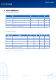
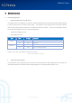
Table Of Contents

SGW101X Series
@2019 | SG Wireless Limited
Confidential Proprietary
Website : www.sgwireless.com
8
R
PD
Pull-down Resistance
11
13
16
kΩ
i. Serial interfaces
The SGW101X series provide the following serial communication interfaces:
o 2x UART interfaces: 4-wire universal asynchronous receiver/transmitter interface used for AT command interface,
data communication, and u- connect software upgrades using the Software update +UFWUPD AT command.
o 3x SPI interfaces: Up to three serial peripheral interfaces can be used simultaneously.
o 1x QSPI interface: High speed interface used to connect to the external flash memories.
o 2x I2C interfaces: Inter-Integrated Circuit (I2C) interface for communication with digital sensors.
o 1x I2S interface: Used to communicate with external audio devices.
o 1x USB 2.0 interface: The USB device interface to connect to the upstream host.
ii. Analog interfaces
8 out of the 48 digital GPIOs can be multiplexed to analog functions. The following analog functions are available:
o
1x 8-channel ADC
o
1x Analog comparator
(*)
o
1x Low-power analog comparator
(*)
REMARK
(*): Only one comparator can be used at any given point of time.
iii. Module Reset
The modules can be reset using one of the following ways:
o Low level on the nRESET (P0.18) input pin, normally kept high using an internal pull-up. This causes an “external” or
“hardware” reset of the module.
o Using the AT+CPWROFF command. This causes an “internal” or “software” reset of the module.
iv. Debug and Programming interfaces
The SGW101X series modules provide an SWD interface for flashing and debugging. The SWD interface consists of two
pins –SWDCLK and SWDIO.
The SGW101X series modules also support parallel trace output. This allows output from the Embedded Trace Macrocell
(ETM) and Instrumentation Trace Macrocell (ITM) embedded in the Arm Cortex-M4 core of the nRF52840 chip. The ETM