MAC-200 Master Antenna Controller Catalog Number 54-25 © August 2003 SGC Inc.
Thank you for buying your new MAC-200 Master Antenna Controller. The MAC-200 incorporates the very latest American-made technology as well as our experience in having delivered more than 100,000 Smartuners since 1985. It is a stateof-the-art tuner providing a new and unique level of usefulness. The concept of the MAC-200 is quite different from our line of Smartuners.
NOTICES READING THIS MANUAL: The most important sections to read in this manual are MAC-200 SETUP (section 3) and MAC-200 OPERATION (section 4). All users should read and understand this material. Other information such as Theory of Operation is available for those who want to understand their new MAC-200 more completely. ATTENTION: The MAC-200 RF Path is open when power is off in both receive and transmit modes. To prevent damage to transceivers, do not operate with power off to this device.
QUICK START 1. 2. 3. 4. 5. 6. Automatic Mode Programming a. Check auto light on b. Select antenna c. While AUTO LED is blinking, apply RF power d. MAC-200 stores tuning & antenna settings Manual Mode Operation a. Check manual light on b. Select antenna c.
Table of Contents 1 INTRODUCTION ...............................................................4 2 TECHNICAL SPECIFICATIONS ....................................6 3 MAC-200 SETUP ................................................................7 3.1 3.2 3.3 3.4 4 MAC-200 OPERATION ...................................................29 4.1 4.2 4.3 4.4 4.5 4.6 5 POWERING ON THE MAC-200.....................................29 SELECTING THE METER RANGE ..................................
1 Introduction Why did we create the MAC-200? To pull together the essential tools for antenna management for stations with more than one antenna. Discussions with amateurs and professionals have shown that most have more than one antenna, yet the only place where all of these antennas come together is in the radio room. Only there is it possible to manage the antenna in use and provide matching for all of them. Unfortunately, existing tools do not go far enough.
developed over the years with SGC’s Smartuner line of antenna couplers. However, the MAC-200 is an antenna TUNER intended for installation near the transceiver rather than at the antenna feed point.. The MAC-200, located as it is in the radio room at the point where all antenna feed lines come together, provides tuning at the end of the antenna feed line rather than at the optimum point, the antenna feed point.
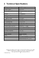
2 Technical Specifications HF Frequency Range Power Input Number of Inputs Revolving Memory Bins Number of Outputs Network Impedance Range Longwire feedline Balanced Output VSWR DC Input Requirement DC Operating Range Input Current Random Set Time Recurrent Set Time Antenna Length (Long Wire) Installation Operating Temperature Size Weight Case Construction Meters Cable Connections 1.8-60Mhz 1.5-200 watts PEP 1 type SO239 168 5 – 1 End Fed, 1 Balanced Feed, 3 Coaxial Pi Configuration .
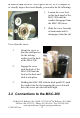
3 MAC-200 Setup 3.1 Mechanical Design The MAC-200 is in an aluminum case. RF and DC power come through the back of the case. Internal construction is normal for fixed location use. Corrosion-resistant hardware and passive alloys are used throughout. For 99% of installations, the factory settings for the internal jumpers will be correct. 3.1.
In order to open the MAC-200 to get at the JP1 or JP3 jumpers or to visually inspect the circuit boards, you need to do the following: 1. Loosen the cover lock on the back panel of the MAC-200 until the washer disengages from the MAC-200 cover. 2. Slide the cover forwards or backwards until it disengages from the rail. To re-close the cover: 1. Orient the cover so that the small groove for the locking washer is at the back of the MAC-200 2.
All connections to the MAC-200 are made on the back panel. NOTE: Under normal operating conditions, it is good practice to connect a dummy load to one of the 50-Ohm antenna connectors in order to have it available for test purposes. 3.2.1 12 VDC Power ATTENTION: The MAC-200 RF Path is open when power is off in both receive and transmit modes. To prevent damage to transceivers, do not operate with power off to this device.
Chassis Ground 12 VDC The MAC-200 has a miniature power input jack on the back panel. Any voltage from 10 to 18.5 VDC is suitable for operation. Average current draw will be approximately 230 milliamps. The MAC-200 should be powered from the same power source used to supply your transceiver to ensure that it is energized whenever the transceiver is in operation. 3.2.2 RF Input from your transceiver A standard SO-239 jack is for RF Input from your transceiver. 3.2.
The chassis ground should be connected to a suitable station safety grounding system. 3.2.4 Connecting Antennas to the MAC-200 3.2.4.1 Coax antenna feeds SO-239 Connectors for Coaxial Cable Three SO-239 connectors are provided for antennas fed with Coaxial cable. SGC recommends that one connector be reserved for a dummy load if possible for testing purposes. From the front panel, these three connections correspond to switches 3, 4, and 5. . PO Box 3526, Bellevue, WA. 98009 13737 SE 26th St.
3.2.4.2 Long Wire Connections Long Wire (unbalanced) RF Hot Connection Long Wire (unbalanced) RF Ground Connection The long wire connection starts from two lugs on the back panel labeled ‘Longwire.’ They correspond to antenna selection switch 2 on the front panel. An RF ground connects to the lug labeled RF GND. When using a single wire ‘counterpoise, it should be 5-10% longer than the random length long wire.
Balanced Feed Line Connection The balanced feed connections corresponding to antenna switch 1, will accept any form of balanced feed line for an external antenna. . PO Box 3526, Bellevue, WA. 98009 13737 SE 26th St. Bellevue, WA. 98005 Toll Free: 800-259-7331 * Phone: 425-746-6310 * Fax: 425-746-6384 www.sgcworld.com * Email: sgc@sgcworld.
3.2.4.4 Multiple Antenna Connections The MAC-200 was designed specifically to allow multiple antenna types with multiple feed lines to be controlled from a single location. Up to five different antennas can be connected, three fed by coaxial lines, one with an unbalanced line, and one with a balanced line. All of these are switch selectable from the front panel. PO Box 3526, Bellevue, WA. 98009 13737 SE 26th St. Bellevue, WA. 98005 Toll Free: 800-259-7331 * Phone: 425-746-6310 * Fax: 425-746-6384 www.
3.3 Antennas and the MAC-200 The MAC-200 can accommodate a wide variety of antennas providing a convenient way to switch between them and to tune them, all in the same box. 3.3.1 Optimum Coupling The MAC-200 incorporates a coupler internally to provide for tuning on a variety of antennas under direct control of the user. This is a compromise location. The optimum location is the antenna feed point where the impedance match keeps SWR on the feed line to an absolute minimum. . PO Box 3526, Bellevue, WA.
3.3.2 Connecting Multiple Antennas The MAC-200 is provided with 3 SO-239 connectors, one RFHot/RF-GND pair, and one balanced feed connection. The SO-239 connectors are intended to connect to a normal Coaxial feedline. Any antenna that is properly setup for Coax feed can be connected to one of these connectors.. One common benefit of having a switchable antenna controller is the ability to leave a dummy load connected so that you can switch to it conveniently at need.
at the feed point. Typical balanced antennas are dipoles and loops. Unbalanced antennas need an RF Ground or counterpoise to create electrical balance and depend on the quality of the ground for a high quality radiated signal. Without a good quality ground, unbalanced antennas will cause interference, lead to RF in the radio room, and be of very low efficiency due to high losses in the ground. Typical unbalanced antennas are long wires and verticals. 3.3.
http://www.sgcworld.com/ftp/Books/hfguide.pdf For detailed technical information about antennas, the consistently best source is the ARRL Antenna Handbook. 3.3.5.1 Dipoles Balanced antennas can be connected to the balanced line connections on the back of the MAC-200. Some balanced antennas, such as the doublet, have a coax feed at the center point. Simply connect your coax feed line to the MAC-200 at connectors 3, 4, or 5. PO Box 3526, Bellevue, WA. 98009 13737 SE 26th St. Bellevue, WA.
Stealthy antennas are built in a variety of ways. A simple example is a roof-mounted dipole with its ends bent 90 degrees and fed from the MAC-200. 3.3.5.2 The Inverted V Antenna The inverted-V antenna can be fed with ladder line run from the balanced line connection on the MAC-200, but it is also commonly fed from coaxial cable with the center conductor to one side and the shield to the other. . PO Box 3526, Bellevue, WA. 98009 13737 SE 26th St. Bellevue, WA.
3.3.5.3 Dipoles with Matching Lines Some antennas, such as the G5RV, use a section of ladder line as a matching device. These transform the impedance of feed point to something near 50 ohms. Usually, the ladder line terminates in a 1:1 balun. The Coaxial line from the transceiver connects to the balun. The MAC-200 can feed this connection directly from one of the coax ports or you can remove the balun run the ladder line directly to the MAC-200 balanced feed line port. PO Box 3526, Bellevue, WA.
3.3.5.4 Long Wires & Inverted Ls Long wire and inverted L antennas are unbalanced antennas. They are fed from the upper LONGWIRE connection directly with a single wire. CAUTION: Unbalanced antennas are radiating from the line as soon as they leave the MAC-200. Minimize the amount of wire inside the radio room to prevent interference with electronic equipment. Minimizing power will also minimize interference caused by this kind of antenna. . PO Box 3526, Bellevue, WA. 98009 13737 SE 26th St. Bellevue, WA.
More than any other factor, a good RF ground will help to improve the radiated signal from these antennas and minimize RFI generated by the antenna. As a minimum, an RF Ground can consist of a wire 5-10% longer than the wire antenna and laid out so that it does not cross over itself or form a loop. A far better RF ground can be constructed by adding ground radials connected to the RF GND lug on connector 2 of the MAC-200. 3.3.5.
the antenna. This type of antenna should be connected to one of the three SO-239 connectors on the MAC-200 (switches 3, 4, or 5). Any vertical antenna fed with Coaxial cable can be connected in this way. Home made vertical antennas are commonly made in one of two ways. A very common type of construction builds the radial system at the base of the antenna. Flag pole antennas are normally built in this way. Coax line can be run from the MAC-200 to the base of the antenna.
3.3.5.6 Loops Loop antennas are balanced antennas that are very simple to feed from a balanced feed line. Ideally, a Smartuner would be at the loop feed point, but when using the MAC-200, balanced feedline will minimize SWR between the MAC-200 and the loop. A loop would typically be connected to the MAC-200 at the BALANCED connection (switch position 1). Loops can be conveniently arranged either horizontally or vertically, but the feeding arrangement from the MAC-200 would be the same.
3.3.5.7 Beams Typically, the radiating element of a beam is a dipole antenna fed with coaxial cable. Connecting a beam to the MAC-200 is accomplished by connecting the coax to positions 3, 4, or 5. 3.3.6 Tips & Tricks 1. The most frequent source of problems in unbalanced antenna systems is the RF Ground. RF grounding is frequently misunderstood and poorly implemented. See our book The HF User’s Guide available free for download from http://www.sgcworld.com/ftp/Books/hfguide.pdf . 2.
3.3.7 References on Antennas 3.3.7.1 From SGC SGC, HF User’s Guide, available free from http://www.sgcworld.com/ftp/Books/hfguide.pdf SGC, Stealth Antenna Manual, available free from http://www.sgcworld.com/ftp/Books/STEALTHman.pdf 3.3.7.2 Books Carr, Joseph, Practical Antenna Handbook, 3rd Edition, McGrawHill, New York, 1998. Hale, Bruce, Editor, The ARRL Handbook, ARRL, Newington, Ct., 1988. Hall, Gerald, Editor, The ARRL Antenna Book, ARRL, Newington, Ct.
3.4 The Golden Rules of HF Installation These rules apply to all types of stations, including base, mobile, airborne and marine. They are very important for planning and installing your HF system, if you want to achieve good communications. 1. 2. 3. 4. 5. Install the transceiver as close to the operation site and power supply system as possible (whether it is an external power supply or battery system). The antenna must be installed in an open space and as far as possible from your operating point.
• • • • HF User’s Guide Go Mobile at 500 Watts Stealth Antennas Smartuner Antenna Coupler Manuals PO Box 3526, Bellevue, WA. 98009 13737 SE 26th St. Bellevue, WA. 98005 Toll Free: 800-259-7331 * Phone: 425-746-6310 * Fax: 425-746-6384 www.sgcworld.com * Email: sgc@sgcworld.com © 2003 SGC Inc.
4 MAC-200 Operation 4.1 Powering on the MAC-200 Power Button Momentarily press the Red Power button on the front panel to activate the MAC-200. You should see the LEDs behind the meter displays light up. 4.1.1 Backlighting During power on, the MAC-200 checks to see if the AUTO or MANUAL keys are pressed. If the AUTO key is pressed, meter backlighting is turned ON. If the MANUAL key is pressed, meter backlighting is turned OFF. Default from the factory is backlighting ON.
Backlighting can be turned on or off by pressing the RESET button and holding the AUTO or MANUAL key during microprocessor reset. 4.1.2 Keytones During power on, the MAC-200 checks to see if the 20W or 200W keys are pressed. If the 20W key is pressed, keytones are turned ON. If the 200W key is pressed, keytones are turned OFF. Default from the factory is keytones ON. The current keytones settings are stored and will be recovered whenever the MAC-200 is started.
4.2 Selecting the Meter Range Meter Range Selection The meter range selection is made on the two push button switches to the left of the meters. Press the switch labeled 20W to activate a 20 watt range. Press the switch labeled 200W to activate the 200 watt range. No harm will come to the meters if the wrong range is activated for the power applied. When a given range is selected, a small LED will light above the switch to indicate which range is currently selected.
Switch Number 1 2 3 4 5 Antenna Balanced Antenna Long Wire Antenna Coax 3 Coax 4 Coax 5 4.4 Auto vs. Manual Antenna Selection The AUTO and MANUAL buttons control the operation of the microprocessor in selecting an antenna. A small LED over each switch indicates the current operating mode. In AUTO mode operation the MAC-200 remembers not only the frequency, but the antenna. The tuner will save the selected antenna along with the tuner settings when a successful match is found.
Antenna settings are kept in a special set of bins. Only one antenna may be stored in each bin. The upper frequency limit on each bin is given in the table below: Freq (Mhz) 2.836 5.754 8.760 12.653 16.626 19.600 23.488 26.431 30.000 >30.000 NOTE: Actual transition frequencies may vary slightly with temperature and aging. When changing the selected antenna in AUTO mode, the LED above the AUTO switch will blink for 10 seconds after a new antenna is selected.
feed point impedance with frequency is particularly high. This will be particularly common with High-Q, narrow bandwidth antennas. 4.5 Front Panel Reset-Lock operation The LOCK button when engaged (the small LED next to the button is on), tells the coupler to ignore all instructions to tune. It will not react to a change in any sensor. All front panel buttons will be locked out except for the POWER button and the meter range selection buttons.
4.6 Do-it-Yourself Light Bulb Test Any time that a transmitter is used, it must be outputting into a load. A load is anything that the output power can be pumped into. If the transmitter is operated without any sort of load connected, the final amplifier stage could become severely damaged. You should never test a transmitter on the air for the first time, if you are unsure about how to operate it, and if you are unsure whether it is working properly. You could create harmful interference to other stations.
as well as an oilcan dummy load. The result is that RF will “leak” out; we have heard a few stories of amateurs who were heard around town while operating their transmitters into a light-bulb dummy load. If you use this system, make sure that you test the equipment on a clear, harmless frequency (NEVER test with the transmitter set on an emergency frequency, such as 2182 KHz).
RADIO TEST PROCEDURE 1. 2. 3. 4. 5. . Connect the transceiver light bulb load to the radio RF in/out jack. Turn on the radio and set the CW mode. Key the PTT switch on the microphone and look at the light bulb. If the light bulb load is connected and the radio is transmitting, the light should turn on. Set the radio to SSB mode. Key the PTT switch on the microphone and talk into the microphone. Notice that the light turns on when you talk. PO Box 3526, Bellevue, WA. 98009 13737 SE 26th St. Bellevue, WA.
COUPLER TEST PROCEDURE 1. 2. 3. 4. 5. 6. Connect the coupler to the radio. Connect coupler light bulb load to Smartuner coupler antenna output. Turn on the radio and the Smartuner coupler. Set the radio to the CW mode. Key the PTT switch on the microphone and look at the light bulb. The light should turn on if the coupler has completed its tuning cycle and if the radio is transmitting. For further testing, follow steps 4 & 5 of the radio test procedure.
5 Theory of Operation The MAC-200 tuner is built around two basic coupler networks, the L & PI. Note that the L network as viewed from the transceiver may be configured as either “C in” or “C out,” whichever is required by the load. In either case, the end of the network containing the shunt C element will be the higher impedance end of the network. L Networks: Pi Network 5.
wide variety of antennas. The versatile MicroTune™ software offers these special functions: 1. 2. 3. 4. 5. The coupler is activated whenever forward power is present. In addition to sampling VSWR to determine if the coupler should retune, it also does a frequency comparison. This causes the coupler to tune whenever the transmit frequency changes independent of the VSWR reading. Many tuning paths test different antenna situations.
5.1.1 Tuning Process An array of detector devices in the MAC-200 monitor the antenna system impedance, reactance, and the VSWR when RF power is applied. The coupler also monitors forward power, since the control computer requires an indication of both forward and reflected power in order to allow tuning to proceed. The forward power detector is a check to ensure that the measurements made are applied RF and are not spurious signals from the data conversion system.
5.1.2 Impedance Detector RF transformers T1 and T3 drive the impedance bridge that is balanced at 50 ohms. T3 samples the line current and thus D7 outputs a negative DC level proportional to line current. A tertiary winding on transformer T1 provides a line voltage sample to D2 that provides a positive voltage proportional to line voltage.
5.1.3 VSWR Detector A directional coupler is formed from current transformer T2 and voltage transformer T1, with termination resistors R33, R34, R35, and R36. The coupler is inserted in the 50-ohm transmission line between the input connector, ST2 RF - ST3 GND, and the tuning network. Forward power is measured across R33, R34 and reflected power is measured across R35, R36.
5.1.4 Phase Detector A phase detector consists of T3, A1, and their associated components. This detector indicates the state of any reactance associated with the antenna coupler as noted from the generator. A line current sample is compared in phase with a voltage sample in a double balanced mixer. Output polarity varies negative or positive depending on the reactance of the antenna.
5.1.5 Central Processing Unit (CPU) A tune-up algorithm implements antenna matching. It is designed using the MC68HC711E9 microprocessor that features a versatile instruction set, RAM, and EEPROM (memory which is saved after the coupler is turned off). The antenna coupler relays are controlled by latches U6 and U7, which receive serial data input directly from the CPU, and Q5. During operation, data is transferred into the CPU from the A to D ports and the Input Capture port (measures RF frequency).
tuned condition. When the tuning algorithm is complete, the CPU saves the settings in its EEPROM, which is addressed by the applied RF frequency. This non-volatile memory table is the basis of the exclusive learning feature of the MAC-200. After it has stored and latched the network status, the CPU waits for RF to cease transmitting and returns to the Stop mode. When RF is re-transmitted, the first step in the tuning algorithm is to measure the frequency of the signal passing through the coupler.
5.1.6 Initialization The microcomputer is usually in the Stop mode and requires an interrupt signal (XIRQ) to start program implementation. The XIRQ comes from the RF detector circuitry. This line, going low, will wake the CPU. 5.1.7 Jumper Settings JP1 in the NO (default) position JP3 in the YES (default) position The MAC-200 may be bypassed for broadband (un-tuned antenna) scanning in receive mode. All you need to do is press the reset button or turn power off and on.
selective calling protocols, or for Automatic Link Establishment (ALE). The default is: Tuning Out In Rcv: [NO]. Jumper JP3 bypasses the coupler’s memories. This means that each time the coupler is used on a different frequency, it will retune rather than use previously stored information. The default is: Tune From Memory: [YES]. 5.1.8 Program Description When DC power is applied, the computer initializes the processor registers in accordance with the hardware.
5.1.8.1Auto Mode In the Auto Mode, the MAC-200 will select the proper antenna as well as the proper tuning settings for the antenna from memory if possible. Detecting forward power. Once forward power is detected and IF the MAC-200 is switched to AUTO, the current coupler settings are sent to the relays and the proper antenna is chosen for operation. Next, the VSWR is checked and the frequency measured.
Signaling “no-tune.” Should the initial primary tuning sequence prove unsuccessful, secondary algorithms are attempted until all possible routines have been exhausted. If, after the secondary attempts, the coupler still cannot achieve a proper VSWR, the program branches to a “no-tune” program. Here, the LED’s and remote tune indicator will blink on and off for about 15 seconds to tell the user a proper VSWR could not be found.
5.1.8.2Manual Mode When the MAC-200 is operating in manual mode, antenna selection is made from the front panel switches. 5.1.9 Tuning Paths As mentioned previously, various tests are executed to determine the most logical tuning sequence to be performed. Dependent on the test results, additional tests and appropriate subroutines are executed throughout the tuning process.
5. 6. the input impedance with input capacitance until a low VSWR is measured of less than 2:1. This process will continue until the VSWR has climbed back to higher than 2:1 or the impedance has become high. The settings that gave the lowest VSWR have been kept in memory and are now recalled to verify it is a low VSWR At this point the tune indicators are engaged.
5.1.9.2 Antenna Too Long Once the coupler has verified RF power, the tuning sequence proceeds as follows: 1. 2. 3. 4. Output capacitance is added until the phase switches to capacitive. At this point, series inductance is added until the antenna is no longer capacitive. Fine tuning is performed by trying a small amount of input capacitance (this may or may not be required). At this point, the program executes the same as step 5 (antenna too short).
NO - In this position the coupler will keep the required tuning data and will change nothing whether in receive or transmit. If typical operation is out of band duplex, Yes would be most likely to give better performance. If in band operation is typical and duplex or simplex is the predominant mode of operation, then No is usually the better choice. 5.1.9.
the best match. We suggest starting with JP3 in the Yes position. If operation is as expected, don’t change it. 5.1.10 Internal B.I.T.E.* LEDs *Built In Test Equipment FRONT FWD PHZ 2:1 L’Z’ TND TND This LED will light when the tuner has found an acceptable match. It will remain lit until conditions have changed which will cause the tuner to find a different match. (i.e. A new transmit frequency has been detected, or tuner has been reset.) L’Z’ This LED shows the status of the antenna impedance.
2:1 This LED will light when the VSWR is greater than 2:1. It will go out when VSWR is less than 2:1. PHZ This LED indicates the status of the antenna reactance. When lit, reactance is inductive. When off, reactance is capacitive. FWD This LED indicates the presence or lack of RF power from the radio. When transmitting, the LED will light to indicate RF detected. The LED should be dark when receiving.
5.2 Schematics . PO Box 3526, Bellevue, WA. 98009 13737 SE 26th St. Bellevue, WA. 98005 Toll Free: 800-259-7331 * Phone: 425-746-6310 * Fax: 425-746-6384 www.sgcworld.com * Email: sgc@sgcworld.
PO Box 3526, Bellevue, WA. 98009 13737 SE 26th St. Bellevue, WA. 98005 Toll Free: 800-259-7331 * Phone: 425-746-6310 * Fax: 425-746-6384 www.sgcworld.com * Email: sgc@sgcworld.com © 2003 SGC Inc.
. PO Box 3526, Bellevue, WA. 98009 13737 SE 26th St. Bellevue, WA. 98005 Toll Free: 800-259-7331 * Phone: 425-746-6310 * Fax: 425-746-6384 www.sgcworld.com * Email: sgc@sgcworld.
PO Box 3526, Bellevue, WA. 98009 13737 SE 26th St. Bellevue, WA. 98005 Toll Free: 800-259-7331 * Phone: 425-746-6310 * Fax: 425-746-6384 www.sgcworld.com * Email: sgc@sgcworld.com © 2003 SGC Inc.
5.3 Component Location . PO Box 3526, Bellevue, WA. 98009 13737 SE 26th St. Bellevue, WA. 98005 Toll Free: 800-259-7331 * Phone: 425-746-6310 * Fax: 425-746-6384 www.sgcworld.com * Email: sgc@sgcworld.
PO Box 3526, Bellevue, WA. 98009 13737 SE 26th St. Bellevue, WA. 98005 Toll Free: 800-259-7331 * Phone: 425-746-6310 * Fax: 425-746-6384 www.sgcworld.com * Email: sgc@sgcworld.com © 2003 SGC Inc.
. PO Box 3526, Bellevue, WA. 98009 13737 SE 26th St. Bellevue, WA. 98005 Toll Free: 800-259-7331 * Phone: 425-746-6310 * Fax: 425-746-6384 www.sgcworld.com * Email: sgc@sgcworld.
SGC LIMITED PRODUCT WARRANTY (1 Year Parts and Labor) And SOFTWARE LICENSE You have purchased an SGC product together with a license to use the software installed in that product. Please return the warranty registration card that accompanies this product, so that we can assure that you receive proper warranty service and important notices that may affect the product.
A Perfect Complement to the MAC-200 The SG-2020 Use it at your base with the MAC-200 or in your backpack or travel bag. The SG-2020 goes where you want to go! Specifications Operating Modes Frequency Range Dimensions Approximate Weight DC Voltage Total current (receive) Transmitter power USB, LSB and CW 1.8-29.7 MHz 7.25”L x 6”W x 2.75”H 18.5cm x 15cm x 7cm 4.5 lbs. (2kg) 10-18 VDC Typical 400mA Adjustable from 0-20W PEP All the Power you’ll need for base, backpack or business travel © 2003 SGC Inc.