The Zero Power Smartuner Catalog Number 54-26 April 2004
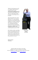
Thank you for buying your new SG211 Antenna Coupler. The SG-211 incorporates the very latest American-made technology as well as our experience in having delivered more than 100,000 Smartuners since 1985. It is a state-of-the-art tuner providing a new and unique level of usefulness. The concept of the SG-211 is quite different from the rest of our line of Smartuners. It is a unique departure designed to provide flexible matching capabilities in a portable environment where power is at a premium.
SG-211 User’s Manual Warnings IMPORTANT NOTE: A random antenna wire will radiate RF. Not only is this an RF Hazard within the station, but it can cause local interference both within the station and in the vicinity depending on your power level. CAUTION: Unbalanced antennas are radiating from the line as soon as they leave the SG-211. Minimize the amount of wire inside the radio room to prevent interference with electronic equipment.
SG-211 User’s Manual Quick Start/Reference © 2004 SGC Inc.
SG-211 User’s Manual Table of Contents 1 INTRODUCTION ................................................ 5 1.1 1.2 2 SPECIFICATIONS............................................. 5 MECHANICAL DESIGN ................................... 7 SG-211 SETUP ..................................................... 8 2.1 CONNECTIONS TO THE SG-211 ...................... 8 2.1.1 RF Input from your transceiver................ 8 2.1.2 Antenna and RF Ground Connections ..... 9 2.2 BATTERY REPLACEMENT.........................
4.2 4.3 4.4 4.5 SG-211 User’s Manual THE MATCHING NETWORK.......................... 36 THE SENSOR ................................................ 37 THE RELAY DRIVER MATRIX ...................... 38 MICROPROCESSOR ....................................... 39 5 COMPONENT LOCATION............................. 41 6 SCHEMATICS ................................................... 43 7 STANDARD WARRANTY............................... 48 © 2004 SGC Inc.
SG-211 User’s Manual 1 Introduction 1.1 Specifications The SG-211 is a revolution. You’ve never seen a coupler so light weight or so flexible. Never has there been one so easy to carry and use. And NEVER have you seen one that will tune for 5 years on a single set of AA cells! © 2004 SGC Inc.
SG-211 User’s Manual HF Frequency Range: Power Input Range: (approximate) Minimum Sensitivity Memory bins: Input Impedance Range: VSWR: DC Input Requirement: Input Current: Random set time: Recurrent set time: Antenna Length: Installation: Operating Temperature: Size: Weight: Case Construction: Antenna types: Power Source Front Panel Connections Rear Panel Connections Indicators 1.8-60 MHz 60 watts (PEP) 30 watts key-down 30 watts (PEP) with short antennas below 3.
SG-211 User’s Manual 1.2 Mechanical Design The SG-211 is in an Irridited Aluminum case. The RF input connector is an SO-239 on the front of the case. RF Output is from balanced and unbalanced connectors on the back. Internal construction makes the SG-211 suitable for portable or fixed location use. Corrosionresistant hardware and passive alloys are used throughout. © 2004 SGC Inc.
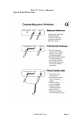
SG-211 User’s Manual 2 SG-211 Setup Setup on the SG-211 is so easy there is almost nothing to do. It comes with AA batteries already installed. All you need to do is connect the coax from your transceiver, attach your antenna to the terminals on the back, and the SG-211 is ready to go. 2.1 Connections to the SG-211 2.1.1 RF Input from your transceiver RF input to the SG-211 is through a standard SO-239 connector on the front. Choose good quality coaxial cable with a PL-259 connector.
SG-211 User’s Manual 2.1.2 Antenna and RF Ground Connections A wide variety of antennas can be connected to the SG211. A set of wing nuts for connecting balanced or unbalanced antennas is provided on the back. Optimum use of the SG-211 Smartuner is to put it directly at the antenna feed point. This may require enclosing it in a waterproof enclosure to protect it from the weather. Either a balanced or an unbalanced antenna can be connected directly to the wing nuts provided on the back of the coupler.
SG-211 User’s Manual When feeding an unbalanced antenna directly, the RF Ground lug is connected with a jumper strap to one side of the balanced feed and the other side of the balanced feed is used for RF Hot. If you are feeding your antenna with coaxial cable, then the cable is connected to the back panel by connecting the center conductor to the right RF Out connection and the braid to the Chassis Ground with a jumper to the left RF Out connection as shown below. © 2004 SGC Inc.
SG-211 User’s Manual A short pigtail connector with an SO-239 female connector on it will make it easier to use Coaxial cable with the SG-211. 2.2 Battery Replacement To replace the batteries inside the SG-211, you must unscrew the cover and remove it. The screws are on the left and right sides of the SG-211 as shown below. Two Cover Screws on each side, none on front and back The batteries are in two battery holders on the SG-211 circuit board. Any suitable alkaline AA batteries may be © 2004 SGC Inc.
SG-211 User’s Manual used. We recommend using the highest quality alkaline AA batteries available to assure the longest life with no battery leakage that could damage the circuit board. Batteries © 2004 SGC Inc.
SG-211 User’s Manual 3 Antennas and the SG-211 The SG-211 can accommodate a wide variety of antennas. 3.1 Optimum Coupling Optimum use of the SG-211 is to place it at the antenna feed point. This keeps SWR on the feed line to an absolute minimum. 3.2 Connecting Antennas The SG-211 is provided with an SO-239 connector on the front panel for RF in. It has balanced and unbalanced connections on the back panel. © 2004 SGC Inc.
SG-211 User’s Manual The SO-239 connector is intended to connect to a normal Coaxial feedline. Unbalanced antennas, such as a long or random wire, are fed by connecting the radiator to the right RF Out connection and the RF Grounding system to the left RF Out and Chassis Ground. IMPORTANT NOTE: Antenna wire connected to the SG211 directly will radiate RF. This is an RF Hazard and it can cause local interference within the station and in the vicinity depending on your power level.
SG-211 User’s Manual 3.3 Balanced vs. Unbalanced Antennas The distinction between balanced and unbalanced antennas is that balanced antennas are electrically balanced at the feed point while unbalanced antennas require an RF Ground to provide the balance. Dipoles and loops are typical balanced antennas. Unbalanced antennas need an RF Ground such as a radial wire system or a counterpoise to create electrical balance. They depend on the quality of the ground for a maximum radiated signal.
SG-211 User’s Manual 3.4 Antenna Recommendations There are many ways to connect antennas for use. Here are some common examples that can help you get started with your SG-211. For additional information about antennas, we recommend that you obtain a copy of our HF User’s Guide from our website at http://www.sgcworld.com/ftp/Books/hfguide.pdf For detailed technical information about antennas, the consistently best source is the ARRL Antenna Handbook. 3.4.
SG-211 User’s Manual 3.4.2 The Inverted V Antenna The Inverted-V antenna can be fed with ladder line run from the balanced line connection on the SG211. It is also commonly fed from coaxial cable with the center conductor to one side and the shield to the other. 3.4.3 Dipoles with Matching Lines Some antennas, such as the G5RV, use a section of ladder line as a matching device. The ladder line transforms the feed point impedance to something near 50 ohms at the antenna’s design frequency.
SG-211 User’s Manual When operated away from the design frequency, these antennas need a tuner such as the SG-211 to match the coaxial line from the transceiver. The SG-211 can be used with either coaxial cable on output to the balun or direct connected to the ladder line section with the balun removed. 3.4.4 Long Wires & Inverted Ls Long wire and inverted L antennas are unbalanced antennas. They are fed from the right RF Out connection directly with a single wire.
SG-211 User’s Manual power will also minimize interference caused by this kind of antenna. More than any other factor, a good RF ground will help to improve the radiated signal from these antennas and minimize RFI generated by the antenna. As a minimum, an RF Ground can consist of a wire 510% longer than the wire antenna and laid out so that it does not cross over itself or form a loop.
SG-211 User’s Manual 3.4.5 Vertical Antennas A vertical antenna may be connected to the SG-211 in a number of ways. Vertical antennas require an RF Ground system to function properly, but this may be incorporated into the design of the antenna itself. A typical vertical antenna is the GROUND PLANE that includes radials in the design. This, and many other vertical antennas use an SO239 connector or equivalent to feed the antenna.
SG-211 User’s Manual Home made vertical antennas are commonly made in one of two ways. A very common type of construction builds the radial system at the base of the antenna. Flagpole antennas are normally built in this way. Coax line can be run from the SG-211 to the base of the antenna. The center lead of the coax will feed the radiating element in the flagpole vertical while the coax shield will be connected to the RF grounding system.
SG-211 User’s Manual The RF ground system is connected to the Chassis ground which should be connected by a jumper to the left RF Hot post. RF Ground system connection If you are using coaxial cable to connect the antenna, then the center conductor goes to the right-most RF Hot post and the braid goes to the left most which is jumpered to the Chassis ground post as shown. A properly installed antenna should not have RF power getting on the outside of the coaxial line. © 2004 SGC Inc.
SG-211 User’s Manual 3.4.6 Loops Loop antennas are balanced antennas. They are very simple to feed from balanced feed line. Ideally, the SG211 will be at the loop feed point, but when it must be at some distance from the feed point, balanced feedline will tolerate the SWR better between the antenna and the SG211 than will coaxial cable. A loop is connected to the SG-211 at the two RF Out connectors. Loops can be conveniently arranged either horizontally or vertically. The feeding arrangement is the same.
SG-211 User’s Manual conductor and the other side of the feed point to the coax shield. 3.4.7 Portable Antennas Portable whip antennas make excellent radiators and can be used in a number of configurations. Examples include fixed whip antennas like SGC’s SG-307 whip and 10 foot collapsible whips available from a number of vendors. One popular antenna uses a whip erected as a vertical antenna with radial wires extending from its base.
SG-211 User’s Manual Another antenna built using whips is a horizontal dipole with two whips, one on each side of the feed point mounted to create a balanced dipole. A pair of SG-307 whips in this configuration will be tunable from 1.8 to 60 Mhz. Ten foot collapsible whips will be tunable from 3.5 to 60 Mhz. Representative sources for the equipment you will need to assemble one of these portable antennas are: © 2004 SGC Inc.
SG-211 User’s Manual Tripod Mast Tripod&Mast Tee Mount Whips Buddipole Tripod Buddipole Mast 16 Foot Buddipole Mast 12-30 Foot Painter’s Pole 6 Foot Portable Antenna Stand Center Tee Mount SG-307 Helically Wound Whip 10 & 12 Foot Extra Long Whips Replacement Whips #2701408B AT271/A Collapsible Whip © 2004 SGC Inc.
SG-211 User’s Manual Check the following web sites for current prices and ordering information: APEX MFJ Radio Shack SGC W3FF Brooklyn. NY http://www.mfjenterprises.com http://www.radioshack.com http://www.sgcworld.com http://www.buddipole.com 3.4.8 Beams The radiating element of a beam is a dipole antenna fed with coaxial cable. Connecting a beam to the SG-211 is accomplished by connecting the coax to a coax pigtail. 3.5 Tips & Tricks 1.
SG-211 User’s Manual RF into your other electronic equipment and VICE VERSA. Your other electronics can inject RF Noise into your receiver and obliterate your received signal completely. 3. Plan your antenna installation carefully! 4. Don’t commit to a final installation until you have tried out your antennas in as near to final form as possible. © 2004 SGC Inc.
SG-211 User’s Manual 3.6 References on Antennas 3.6.1 From SGC SGC, HF User’s Guide, available free from http://www.sgcworld.com/ftp/Books/hfguide.pdf SGC, Stealth Antenna Manual, available free from http://www.sgcworld.com/ftp/Books/STEALTHman.pdf SGC, Smartuners for Stealth Antennas, http://www.sgcworld.com/ftp/Books/stealth.pdf 3.6.2 Books Carr, Joseph, Practical Antenna Handbook, 3rd Edition, McGraw-Hill, New York, 1998. Hale, Bruce, Editor, The ARRL Handbook, ARRL, Newington, Ct., 1988.
SG-211 User’s Manual 3.7 The Golden Rules of HF Installation These rules apply to all types of stations, including base, mobile, air-borne and marine. They are very important for planning and installing your HF system, if you want to achieve good communications. 1. 2. 3. 4. 5. Install the transceiver as close to operation site and power supply system as possible (whether it is an external power supply or battery system).
SG-211 User’s Manual design and installation of your HF system, the operator can expect top performance. Further information regarding applications, installation and operation can be downloaded from our website www.sgcworld.com. These publications include: • • • • HF User’s Guide Go Mobile at 500 Watts Stealth Antennas Smartuner Antenna Coupler Manuals 3.8 Do-it-Yourself Light Bulb Test Any time a transmitter is used, its output must go to a load.
SG-211 User’s Manual Unfortunately, when you use a can-type dummy load, you can’t see “what’s happening” with your transmitter. In this case, you can use a light-bulb dummy load to test your transmitter. Here, the light bulb is directly connected to the output of the transmitter and it dissipates the RF energy as light.
SG-211 User’s Manual ATTENTION: Some retuning may take place as the impedance of the light bulb varies with the power level. If the power level is held constant with a continuous carrier such as produced by CW mode operation, the coupler setting will settle after a short period of time. RADIO TEST PROCEDURE 1. 2. 3. 4. Connect the transceiver light bulb load to the radio RF in/out jack. Turn on the radio and set the CW mode. Key the PTT switch on the microphone and look at the light bulb.
5. SG-211 User’s Manual Key the PTT switch on the microphone and talk into the microphone. Notice that the light turns on when you talk. COUPLER TEST PROCEDURE 1. 2. 3. 4. 5. 6. Connect the coupler to the radio. Connect coupler light bulb load to Smartuner coupler antenna out-put. Turn on the radio and the Smartuner coupler. Set the radio to the CW mode. Key the PTT switch on the microphone and look at the light bulb.
SG-211 User’s Manual 4 Theory of Operation 4.1 Antenna Transmitter Antenna Transmitter The SG-211 tuner is built around the L network. An L network as viewed from the transceiver may be configured with the shunt reactance on the input or the output as shown below: No External Power Required The SG-211 automatic antenna tuner is unique. It requires no external source of power. This means that the unit can be located remotely without the inconvenience of additional wiring to provide power.
SG-211 User’s Manual With normal use, the internal batteries have a service life that approaches the shelf life of the batteries themselves. Battery replacement will be required at intervals of five years or more. The very low average current drain is achieved by using low power latching relays that draw power only during the matching process. A very low power standby mode for the sensors and the microprocessor limits standby current to a few microamperes. 4.
SG-211 User’s Manual The output of the L network can be left floating to drive balanced antennas or one side can be grounded for unbalanced antennas. Providing the balun on the input side of the network means that it is normally operated with a matched load. Locating the balun on the output side as in some other tuners, means that the balun sees much more stress with a mismatched load. 4.3 The Sensor Transformers T2 and T3 form a directional coupler.
SG-211 User’s Manual 4.4 The Relay Driver Matrix Page one of the schematic diagram shows the matrix used to drive the relay coils. The latching relays have two coils; one for turn-on and one for turn-off. With 16 relays, the circuit needs to drive 32 coils. A matrix of six columns and six rows allows selection of 36 coils with only 12 microprocessor outputs. © 2004 SGC Inc.
SG-211 User’s Manual A diode pair is associated with each coil. The series diode provides isolation necessary for proper operation of the matrix. The shunt diode prevents voltage spikes on turnoff. Extensive capacitor bypassing is used to prevent RF from interfering with the proper operation of the matrix. On page two of the schematic diagram transistors Q1 through Q12 provide pulldown drive for the rows and pullup drive for the columns of the matrix. 4.
SG-211 User’s Manual Because a flash programmable microprocessor is used, software can be changed without removing the processor or proms. J1 provides connection to the programmer for this purpose. Since the processor is dormant except during the actual matching process, the possibility of generating RF interference in the receiver is eliminated. © 2004 SGC Inc.
SG-211 User’s Manual 7 Standard Warranty SGC LIMITED PRODUCT WARRANTY (1 Year Parts and Labor) And SOFTWARE LICENSE You have purchased an SGC equipment product together with a license to use the software installed in that product. Please return the warranty registration card that accompanies this product, so that we can assure that you receive proper warranty service and important notices that may affect the product.
Description HF Frequency Range Power Input Range (PEP watts) SG-239 1.8 - 30MHz SG-237 1.8 - 60MHz SG-230 1.6 - 30MHz SG-231 1 - 60MHz SG-235 1.8 - 30MHz 1.5-200 3-100 3-200 3-100 3-500 Continuous CW Power (watts) 80 40 80 60 200 Input Impedance Range (ohms) 45-55 45-55 45-55 45-55 45-55 VSWR (Typical) <2:1 <2:1 <2:1 <1.4:1 <1.4:1 13.8 10 to 18.5 13.6 10 to 18 13.6 10 to 18 13.6 10 to 18 13.6 10 to 18 Input Current (average amps) Random Set Times (seconds) 0.23 <2 0.
A Perfect Complement to the SG-211 The SG-2020 Use it at your base or in your backpack or travel bag. The SG-2020 goes where you want to go! Specifications Operating Modes Frequency Range Dimensions Approximate Weight DC Voltage Total current (receive) Transmitter power USB, LSB and CW 1.8-29.7 MHz 7.25”L x 6”W x 2.75”H 18.5cm x 15cm x 7cm 4.5 lbs. (2kg) 10-18 VDC Typical 400mA Adjustable from 0-20W PEP All the Power you’ll need for base, backpack or business travel Mailing: PO Box 3526, Bellevue, WA.