SG-2020 Tr a n s c e i v e r Installation and Operations Manual “No Compromise Communications”
SGC — The SSB People SGC develops, manufactures, and sells high performance single sideband (SSB) communications equipment. Since 1971, the company has sold to the marine, military, aviation, and industrial markets world wide. Over these years, SGC has earned an outstanding reputation for product reliability and for service after sale. The company keeps pace with equipment options, engineering developments, and design requirements.
SG-2020 Tr a n s c e i v e r Installation and Operations Manual “No Compromise Communications” Manual Version 2.01 Software Version 1.06 July 1999 SGC RESERVES THE RIGHT TO MODIFY SPECIFICATIONS WITHOUT NOTICE. SGC Inc. SGC Building, 13737 S.E. 26th St. Bellevue, WA. 98005 USA P.O.Box 3526, 98009 Fax: 425-746-6384 or 746-7173 Tel: 425- 746-6310 or 1-800-259 7331 E-mail: sgc@sgcworld.com Web site: http://www.sgcworld.com i © 1998 SGC Inc.
TABLE OF CONTENTS 1.0 2.0 3.0 4.0 5.0 6.0 7.0 8.0 9.0 10.0 11.0 12.0 13.0 14.0 15.0 16.0 17.0 18.0 19.0 20.
1.0 FEATURES The SG-2020 is a compact low power transceiver with the features and performance you expect in a modern full size transceiver. • • • • • • • • • • • • • • • • • Strong, wide dynamic range receiver Selectivity at 2.7 KHz not less than 60 dB rejection on the adjacent channel RF Speech processing All Band Operation 160 mtrs through 10 mtrs. General Coverage Receiver, 1.8 MHz through 29.
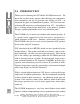
2.0 INTRODUCTION Thank you for choosing the SGC Model SG-2020 transceiver. We know that you have many options when choosing your communications equipment, and we are glad that your choice was SGC - an American designed and manufactured product. SGC has been manufacturing HF transceivers and equipment form 1971. Our philosophy is to bring unique design innovations to the industry; products that give superior performance and at very affordable prices.
any additional current drain. This allows excellent receiver characteristics to be preserved along with long battery life. We believe these benefits will be highly appreciated by operators in the field and other portable operations. The rugged transmitter section provides exceptionally clear, clean audio, and provides excellent performance characteristics. The amplifier has the stress power capability of 40 watts.
3.0 SPECIFICATIONS: SG-2020 SSB HF TRANSCEIVER GENERAL General Operating modes: Receiver Frequency range: USB, LSB and CW 1.8 to 30.
4.0 INSPECTION UPON RECEIPT Upon receipt, open the shipping carton and inspect your SG-2020 transceiver carefully for any signs of damage. After removing all packing materials, check that all exposed controls move freely, and that the enclosure has no dents or scratches. If you notice any damage to the unit, document it completely and contact the shipping company immediately. Save all packing materials for possible future use. 4.
5.1.1 COUPLER TUNE CAPABILITY An external automatic antenna coupler can be automatically tuned in SSB by momentarily depressing the "PBT" push button and then pressing the push button on the microphone within 5 seconds. This will insert the CW tone to allow the coupler to tune. The SG-2020 will transmit a tone as long as the microphone push button is depressed. Once you release the push button on the microphone, the radio reverts to SSB with no tone and normal transmission can resume.
This setup approach will allow any operator to get superb performance under all conditions or pile ups. In CW the SG-2020 supports full break in and performs extremely well. Also, in the electronic paddle mode, the break-in is supported, but has been modified to support the overwhelming demand to extend some hold time after the last character and space, in order to limit the fast back and forth TX-RX cycles.
5.4 AM RECEPTION FOR BROADCAST AND SHORTWAVE Reception of AM broadcast and shortwave stations is very effective by using upper sideband or lower sideband. Choice of either sideband will allow the user to avoid nearby interfering signals. For additional information concerning the SG-2020’s broadcast filter and how to bypass it for broadcast reception in the 400 to 1600 kHz range, see section 15.1. 6.0 INSTALLATION 6.0.1 EQUIPMENT LOCATION The SG-2020 can be affected by strong nearby magnetic fields.
6.0.3 GROUNDING THE RADIO Under normal conditions the radio does not need to be grounded, especially if a dipole antenna or an external coupler is used. In preference and a general rule never ground the radio on the same ground as the coupler, this will avoid harmful RF to come back to the radio. If grounding of the radio is necessary, proceed as described below: Any of the four rear panel screws can be use to attach the ground. 1. remove the desired screw. 2. attach RF ground to ring lug (not supplied). 3.
6.1.1 DESK TOP INSTALLATION A Flip Front Foot is supplied with the radio. This foot can be flipped up to raise the front of the radio 3 inches above the desk level. Additional front flip feet can be ordered separately, catalog number 05-43. 6.1.2 DESK OR BASE MOUNTING (option 05-42) To mount the SG-2020 in a secure installation, use the optional mounting plate in the transverse or longitudinal position a s described below: A. Remove 3 screws in the bottom of the chassis. B.
tions as appropriate. The DC cable should be connected directly to the vehicle battery, rather than to the ignition or accessory circuitry. Route the cable as far away from the ignition wiring and other cables as possible. Keep the length of this cable as short as possible to minimize voltage drop losses.
6.2.3 MOBILE MOUNTING OPTIONS Velcro mobile mounts (option 05-42) with peel-off adhesive are supplied (to be installed by the operator). When using the velcro mount, we recommend the use of a secure cable, which should be attached between the radio chassis (or mounting plate) and the vehicle for added safety. For a more secure and versatile installation, an optional pedestal mount system is also available from your dealer.
7.2 HAM GEAR CW In the development of this product, special attention was given to design a product with excellent CW operation. Two key jacks are provided; one for a straight key (mono jack) and the other for an electronic keyer (stereo jack). The straight key allows the operator full break in capability, and also the transmitter can be keyed by using a separate foot switch or depressing the push button on the microphone.
The SG-2020 will switch between receive and transmit in less than 10 milli seconds and is well suited for this type of data operation. 7.4 MARINE The SG-2020 is an ideal marine radio. Since it is not FCC type approved for this operation, it should be used as an auxiliary hobby radio. The low power requirements enable the unit to operate when other equipment on board may not, (i.e. because of a power failure or major accident at sea).
7.6 COMMERCIAL USE The SG-2020 is a practical radio for commercial applications, because it can be programmed with only a few necessary channels and then locked. The casual or unfamiliar operator can access only these channels through the main tuning knob. Scanning can be easily accessed allowing perfect channel monitoring of only the channels in use.
FIGURE 2 KEY NAME PRIMARY FUNCTION 1. 2. 3. 4. 5. 6. 7. 8. 9. PWR LIGHT LED LCD BARGRAPH SPINNER MEM REV FAST 10. 11. 12. 13. 14. 15. 16. 17. 18. 19. 20. 21. 22. 23. 24. "BW" SPLIT VOLUME RIT RF "XCVE" KEY PAD MIC LED CMD LED (3) SPEED "PBT" NB Power On / Off. Backlight On / Off Noise Blanker Indicator Liquid Crystal Display LED Array Display Main Tuning Control Memory Function Reverse Fast Tuning - adjustable rate .1 kHz, .5 kHz, 1.
8.0 FRONT PANEL (see figure 2) The following legend presents the PRIMARY function of each individual control and indicator. Several controls have secondary functions when used in conjunction with the spinner knob or other buttons, as described in the SECONDARY SWITCH FUNCTIONS chapter of this manual. 8.1 CONTROLS Location of push buttons - (see figure 2) All four main push buttons: FAST, MEM, BW, REV have been designed and located for convenient one-hand operation.
8.1.4 "PBT" (Passband Tuning) The "PBT" button will activate passband tuning. The display will show the passband offset in KHz. Turn the main tuning knob while pressing the "PBT" button to change the passband tuning as desired. This will shift the IF passband relative to the BFO frequency. The adjustment rate is from -1000 Hz to +300 Hz in 100 Hz steps. Shown at left is the effect of the passband tuning. Assume the bandwidth is set at 2.0 KHz.
the amateur bands it is the operator's responsibility to transmit only on modes and frequencies consistent with his or her class of license and regional recommended band plan. In the "XCVE" position the SG-2020 receives and transmits on the same frequency. Press the RIT(Receiver Incremental Tuning) button and the transmit frequency remains fixed while the receive frequency can be varied.
8.1.8 MEM (Memory) The SG-2020 has 20 user accessible memories. The unit comes from the factory with the memories preset to a few frequencies in each amateur band for convenience. However, these preselected frequencies may be changed by the operator at any time desired. Press the MEM button and turn the main tuning knob to step from one stored frequency to another. Tune to a new frequency using the FAST button if the new frequency is some distance from the previous one.
8.1.9 "BW" (Bandwidth) Press the "BW" button. The display will show the receiver bandwidth. Turn the main tuning control while pressing the "BW" button to change bandwidth. It is adjustable from 2.7 KHz to 100 Hz in 100 Hz steps. 8.1.10 MODE SELECTION ("BW" + REV) To display the current operating mode (USB / LSB / CW), press "BW". To select another mode, hold "BW" and momentarily press REV until desired mode appears on the display. Release "BW" to return to frequency display. 8.1.
1. 2. 3. 4. 5. 9.3 any ‘CMD’ + ‘XXX’ combination ‘SPEED’ ‘"PBT"’ ‘MEM’ ‘"BW"’ Tx OUTPUT POWER LEVEL ADJUST (CMD + NB) When pressing CMD and NB simultaneously, but momentarily, Tx output power level is adjustable by rotating the main tuning knob. Adjustment levels are made in increments of approximately one watt, from 0 to 20 watts. To return to the frequency display, press MEM. To enter this setting in the last recalled memory, press FAST + MEM. Accurate calibration is not supported. 9.
Blanking: ‘b’ is displayed (Press MEM to enter). FREQUENCY STEP: .1, .5, 1.0, or 2.5 kHz. FREQ Step: ‘F’ is displayed (Press MEM to enter). 9.7 ADJUST ‘FAST’ INCREMENTAL VALUE (CMD + FAST) While pressing CMD and FAST simultaneously, but momentarily, turn main tuning knob to adjust the incremental value by .1, .5, 1.0, or 10 kHz. To store this value into memory, press MEM. 9.
want the backlight on or off when the radio is turned on. This is done by using the ‘REV’ button to toggle between ‘dl ON’ and ‘dl OFF’. Store the choice by depressing the ‘MEM’ button. Once the ‘MEM’ button is released, a sequential test is performed on each LED and the backlight. The radio then reverts to normal operation. 10.4 LOCKOUT ("PBT" + RIT) To toggle the lockout function on or off, hold "PBT" and RIT simultaneously upon power up.
11.0 BARGRAPH DISPLAY 11.1 POWER / S-METER In receive the bargraph shows relative signal strength in S units. In transmit the output power is also displayed. Hold the “REV” button while transmitting and the reflected power will be displayed. The display returns to forward power indication when the “REV” button is released.
12.0 FRONT PANEL CONNECTORS 12.1 PAD Keyer paddles can be plugged into the 3.5 mm stereo phone jack to utilize the built in electronic keyer. A 3.5 mm stereo plug is required to make proper connections to the paddles. The shell of the plug is ground, the ring is dash and the tip is dot. The keyer is similar to the Curtis type B format iambic keyer. 12.2 KEY A 3.5 mm mono phone jack is provided on the front panel for a straight key. The key sees +5 Volts at a few milli amperes.
13.0 REAR PANEL CONNECTORS (see figure 3 below) 13.1 ANTENNA (rear panel) The antenna is connected to the ANTENNA connector. An SO239 connector is on the transceiver and is intended to be mated with a standard PL-259 coaxial plug connector. The transmitter expects a 50 ohm matched load at the operating frequency. If the load is mismatched, the SWR protection will reduce the output power with minor mismatches or shut the transmitter down with more severe mismatches. 13.2 13.
28 © 1998 SGC Inc SGC Inc. SGC Building, 13737 S.E. 26th St. Bellevue, WA. 98005 USA P.O.Box 3526, 98009 Fax: 425-746-6384 or 746-7173 Tel: 425- 746-6310 or 1-800-259 7331 E-mail: sgc@sgcworld.com Web site: http://www.sgcworld.
14.0 CIRCUIT DESCRIPTION The SG-2020 uses a single conversion up-converting design. The IF is at 60 MHz. Bi-directional circuitry is used in the IF and filter chain. Selectivity is provided by a 7 pole ladder filter at 60 MHz and variable SCAF digital filters at the baseband. The synthesizer is a single loop design. The basic synthesizer uses 10 KHz steps with intermediate steps of approximately 10 Hz obtained through direct microprocessor control of the reference. 14.
Many users believe that just one IF stage (as in the SG-2020) provides inferior performance. Actually, the contrary is true. The less IF stages there are, the less receiver and transmitter spurious frequencies are apparent. Generally, if the design is done right, one IF stage is sufficient. This also provides superior receiver performance. The SG-2020 receiver is equal or better than most transceivers available in the commercial or ham markets. 14.
14.4 CW SIDE TONE The CW side tone level can be adjusted by turning R46 on the exciter printed circuit board. See picture below. R46 Flex Cable Removed Note: The SG-2020 is set to transmit at 650 Hz upper sideband tone. Setting the dial frequency for the same receive and transmit frequency “pressing button RCVE” will transmit a tone frequency of 650 Hz above the carrier frequency (upper sideband). 15.
jumpers over to the alternate position; this will bypass the broadcast filter and enable reception. J6 J7 Speaker removed The broadcast filter is designed to reject any broadcast station that may be in the vicinity of the receiving station using the SG-2020 that could cause interference. In some cases, the rejection may not be sufficient and may be heard in the SG-2020 receiver. Stations using 100 kilowatts within 10 miles may cause excessive interference. 15.
16.0 QUICK TOUR OF USER CONNECTORS There are a total of six 'user accessible' connectors on the SG-2020. Three connectors on the front panel provide connections for microphone, iambic paddle and standard key. The remaining three connectors are located on the rear panel and provide connections for antenna, power and earphones. 16.1 FRONT PANEL CONNECTORS 16.1.1 MICROPHONE This connector is a standard 8 pin microphone connector that is common to all SGC transceivers and others such as the Kenwood MC-43.
16.2 DATA MODE CONNECTION Below is an example of a data mode inter connection. 16.3 REAR PANEL CONNECTORS There are three connectors on the rear panel of the SG-2020 transceiver. 16.3.1 ANTENNA Unlike most solid state transmitters, the SG-2020 is not readily damaged by a mismatch or high SWR. However, intentional operation under mismatched conditions should be avoided.
when transmitting at full output power levels. When operating in receive mode only, a much smaller supply capable of 1 ampere or more will be sufficient. The SG-2020 can be damaged by voltages greater than 18 volts and may shut down if the supply voltage drops below 9 volts. Some wall mounted power supplies do not provide sufficient filtering or regulation and should not be used with the SG-2020.
17.0 ALIGNMENT/TEST PROCEDURES 17.1. PHASE LOCK LOOP ERROR VOLTAGE Required Test Equipment a) Digital Volt Meter Procedure Connect the DVM to the PLL error voltage test point (TP3) on the Exciter PCB and Gnd. Tune the SG-2020 to 29.7 MHz and verify the voltage is less than 16 V. If the voltage is greater than 16 V when tuned to 29.7 MHz adjust spacing between windings of L18. Tune to 1.8 MHz and verify the voltage is greater than 3 V . 17.
RF Input level .3 µV 3 µV 30 µV 3 mV 3V AF output level >200 mV RMS > 2 V RMS > 2 V RMS >2.25 V RMS > 2.25 V RMS 17.4 SET TRANSMITTER BIAS Required Test Equipment a) Digital Volt Meter b) RF Power Meter c) Dummy Load Procedure Tune the SG-2020 to 14.2 MHz. Connect the power meter and dummy load to the SG-2020. Connect the DVM to TP1 & TP2 on the LPA PCB. Ensure the Mode is not CW. With no signal connected to the mic. input activate the PTT line. Use milli volt scale on DVM. Adjust R7 on the LPA for 7 mV .
Adjust C56 on the LPA for minimum reverse swr detector voltage (typically 3 mV). 17.6 FREQUENCY CALIBRATION Is factory set only. Note: Any adjustments made to the SG-2020, besides R46 CW sidetone are NOT covered by the warranty. 17.7 NOMINAL OUTPUT POWER TEST Set output capability of the transceiver by setting the output level to “20”. Set generator to 1300 Hz 20 mV AF input to the microphone connector; measured output power level should be: 1.
17.9 OPENING THE SG-2020 Should it become necessary to open the unit for modification or inspection, please note the following instructions and comments: 1. Remove the three screws on the bottom of the chassis 2. Push the back panel gently toward the front through the case 3. CAUTION: Please note that the speaker is pressed toward the outer case with foam padding. Handle with care when removing the chassis from its case. 4. To reassemble, push gently down on the speaker and push the chassis back slowly.
18.0 PART 40 © 1998 SGC Inc Q11P3 U5P1 U5P2 U5P3 U5P4 U5P5 U5P6 U5P7 U5P8 U5P9 U5P10 U5P11 U5P12 U5P13 U5P14 Q17P1 Q17P2 Q17P3 Q10P1 Q10P2 Q10P3 Q9P1 Q9P2 Q9P3 Q7P1 Q7P2 Q7P3 Q8P1 Q8P2 Q8P3 Q6P1 Q6P2 Q6P3 Q5P1 Q5P2 Q5P3 Q4P1 Q4P2 Q4P3 U10P1 U10P2 U10P3 EXCITER VOLTAGE MEASUREMENTS-RECEIVE (cont.) V DC 0 10.0 0 0 10.0 2.7 2.7 9.7 10.0 0 0 0 5.0 5.0 5.0 5.0 5.0 0 5.0 5.0 0 10.0 10.0 0 0 0.2 0.2 0 0.2 0 9.25 0 10.0 9.25 10.0 10.0 10.0 10.0 0.2 9.0 9.0 0 PART V DC U10P4 2.9 U10P5 4.3 U10P6 2.
18.0 EXCITER VOLTAGE MEASUREMENTS-RECEIVE (cont.) PART U16P4 U16P5 V DC 5.0 0 U16P6 U16P7 U16P8 U23P1 U23P2 U23P3 U23P4 U23P5 U23P6 U23P7 U23P8 Q35P1 Q35P2 Q35P3 Q32P1 Q32P2 Q32P3 U25P1 U25P2 U25P3 U25P4 U25P5 U25P6 U25P7 U25P8 U25P9 U25P10 U25P11 U25P12 U25P13 U25P14 U25P15 U25P16 Q38P1 Q38P2 Q38P3 Q37P1 2.0 2.7 5.0 0 0 5.0 5.0 0 2.0 2.7 5.0 2.6 2.2 10.0 2.2 2.2 10.0 5.0 5.0 5.0 0 0 5.0 0 0 5.0 5.0 5.0 5.0 5.0 5.0 5.0 5.0 0.7 0 0 0.
42 © 1998 SGC Inc SGC Inc. SGC Building, 13737 S.E. 26th St. Bellevue, WA. 98005 USA P.O.Box 3526, 98009 Fax: 425-746-6384 or 746-7173 Tel: 425- 746-6310 or 1-800-259 7331 E-mail: sgc@sgcworld.com Web site: http://www.sgcworld.
43 SGC Inc. SGC Building, 13737 S.E. 26th St. Bellevue, WA. 98005 USA P.O.Box 3526, 98009 Fax: 425-746-6384 or 746-7173 Tel: 425- 746-6310 or 1-800-259 7331 E-mail: sgc@sgcworld.com Web site: http://www.sgcworld.
J2 XMIT CW GND SIDETONE 4 A0 5 EXCITER PCB A1 A2 6 7 8 J1 SPEAKER P6 J6 1 1 4 2 2 5 RED BLK TO VOL CNRL TX AUDIO 1 2 3 AGC FROM VOL CNRL PTT 6 7 8 9 10 VDD 2 3 2 3 4 4 4 5 5 6 6 7 5 6 7 GND 2 3 CS5 + 12V SWITCHED 2 3 4 DATA OUT 5 GND 6 CLK 5 6 7 8 GND N/C 7 9 TUNED 10 N/C 4 8 9 10 DRAFTING: DATE REV 12/98 A DESCRIPTION ORIGINAL DWG AUTH RT 4 5 PHONE 6 MIC GND BLK GND BLK DOT DASH GND WHT/YEL WHT BLK 7 8 P9 J9 1 2 3 1 2 3 P10 J10 1 1
19.0 PCB LAYOUT AND SCHEMATICS COMPONENT LAYOUT EXCITER 45 SGC Inc. SGC Building, 13737 S.E. 26th St. Bellevue, WA. 98005 USA P.O.Box 3526, 98009 Fax: 425-746-6384 or 746-7173 Tel: 425- 746-6310 or 1-800-259 7331 E-mail: sgc@sgcworld.com Web site: http://www.sgcworld.
COMPONENT LAYOUT LPA 46 © 1998 SGC Inc SGC Inc. SGC Building, 13737 S.E. 26th St. Bellevue, WA. 98005 USA P.O.Box 3526, 98009 Fax: 425-746-6384 or 746-7173 Tel: 425- 746-6310 or 1-800-259 7331 E-mail: sgc@sgcworld.com Web site: http://www.sgcworld.
COMPONENT LAYOUT PROCESSOR REAR 47 SGC Inc. SGC Building, 13737 S.E. 26th St. Bellevue, WA. 98005 USA P.O.Box 3526, 98009 Fax: 425-746-6384 or 746-7173 Tel: 425- 746-6310 or 1-800-259 7331 E-mail: sgc@sgcworld.com Web site: http://www.sgcworld.
COMPONENT LAYOUT PROCESSOR FRONT 48 © 1998 SGC Inc SGC Inc. SGC Building, 13737 S.E. 26th St. Bellevue, WA. 98005 USA P.O.Box 3526, 98009 Fax: 425-746-6384 or 746-7173 Tel: 425- 746-6310 or 1-800-259 7331 E-mail: sgc@sgcworld.com Web site: http://www.sgcworld.
COMPONENT LAYOUT DISPLAY 49 SGC Inc. SGC Building, 13737 S.E. 26th St. Bellevue, WA. 98005 USA P.O.Box 3526, 98009 Fax: 425-746-6384 or 746-7173 Tel: 425- 746-6310 or 1-800-259 7331 E-mail: sgc@sgcworld.com Web site: http://www.sgcworld.
50 © 1998 SGC Inc PROCESSOR PCB SCHEMATIC 1 OF 4
PROCESSOR PCB SCHEMATIC 2 OF 4 51 © 1998 SGC Inc
52 © 1998 SGC Inc PROCESSOR PCB SCHEMATIC 3 OF 4
PROCESSOR PCB SCHEMATIC 4 OF 4 53 © 1998 SGC Inc
54 © 1998 SGC Inc LPA PCB SCHEMATIC 1 OF 3
LPA PCB SCHEMATIC 2 OF 3 55 © 1998 SGC Inc
56 © 1998 SGC Inc LPA PCB SCHEMATIC 3 OF 3
EXCITER PCB SCHEMATIC 1 OF 8 57 © 1998 SGC Inc
58 © 1998 SGC Inc EXCITER PCB SCHEMATIC 2 OF 8
EXCITER PCB SCHEMATIC 3 OF 8 59 © 1998 SGC Inc
60 © 1998 SGC Inc EXCITER PCB SCHEMATIC 4 OF 8
EXCITER PCB SCHEMATIC 5 OF 8 61 © 1998 SGC Inc
5R 62 © 1998 SGC Inc EXCITER PCB SCHEMATIC 6 OF 8
EXCITER PCB SCHEMATIC 7 OF 8 63 © 1998 SGC Inc
64 © 1998 SGC Inc EXCITER PCB SCHEMATIC 8 OF 8
DISPLAY PCB SCHEMATIC 1 OF 1 65 © 1998 SGC Inc
19.0 CATALOG ITEMS On the following pages, you will find an updated list of SG-2020 accessories, which includes prices. Please note that price and delivery must be confirmed at the time of order. All items can be ordered directly from SGC using your Mastercard or Visa. Note that some items may not be in stock at the time of the order. Shipping and handling charges for items weighing less than one pound is $12.00 USD (via UPS surface delivery).
5.00 05 0 -1 S G 2 -0 2 ( S 0 W z y v T e a n h d t re s c iA 8 3 1 T -M 0 .T -S H Z ) S G 2 -0 2 S 0 z y e H n h d 2 S t ( e F s S iW -0 T v a B e n rs c e iA 8 1 3 T -M .0 T -S H Z ) $ 6 7 5 0 .
05 4 -2 M e a B S tP n G a 2 e s d o l-u 0 a e n lt s ,M 2 l0 o b i . $ 1 9 9 .5 Mount plate is to be attached at the lower part of the radio to secure as a base, mobile or pedestal mount for both base and mobile installation. Includes four adhesive rubber feet and two, 5 inch Velcro strips for alternate use. Pedestal hardware is not supplied 05 4 -3 a n s t o d o fp t -S G i2 -0 F o lF 2 n rt0 $ 2 9 .5 Flip-foot stand to elevate radio 2 inches; for desk or bench operation.
52 9 -7 C A R U S G E :G E D T R A V S ( E G L 2 -0 e 2 s )S 0 ie r $ 2 1 ,9 5 0 .0 HalliburtonTM aluminum travel case, charcoal grey. Case accommodates one SG-2020 PortaPak unit (catalog number 05-31) with DC/DC charger and adjustable shoulder strap. (Note: not a stock item). 53.00 53 2 -1 POWER SUPPLIES P O W E S R U P 1 S L -Y 0 U :N R E G U L A T E D $ 1 8 9 .5 Model PS-10 direct rectified power supply for 115/230 volts AC, 50/60 Hz. Output voltage nominal 14.
55 0 -5 Ω1 5 0 W )9 ( .t0 f S G 1 -0 T 3 A C T A B IL R O A D B A N D A N T E N 5 N 0 A - $ 7 0 0 .0 SG-103-T tactical antenna, designed for multi frequency medium and long range communication and can be used with any radio. - Operating range: 2-28 MHz. - Maximum power rating 150 watts CW. - VSWR on all frequencies better than 2 to 1. - 90 ft. long for installation as flat-top antenna, inverted ‘V’ or sloper. - Supplied with Ω 50connector, PL-259 and 60 ft. coaxial feed cable.
91.00 91 1 -7 PUBLICATIONS & MANUALS M A N U A S G 2 L -:0 2 0 M -M A N ,T IE N A N C E $ 2 0 .0 Complete installation, operation and service manual containing all necessary servicing, testing and maintenance information. 91 1 -8 S G 2 -0 2 0 Q S C L d a rs $ 1 9 9 .5 Package of 25 attractive SG-2020 QSL cards. Please note that price and delivery must be confirmed at the time of order. 71 SGC Inc. SGC Building, 13737 S.E. 26th St. Bellevue, WA. 98005 USA P.O.
Glossary 10-meters: 15-meters: 20-meters: 40-meters: 160-meters: (+): (-): 72 © 1998 SGC Inc 28.0 - 29.7 MHz 21.0 - 21.450 MHz 14.0 - 14.350 MHz 7.0 - 7.3 MHz 1.8 - 2.0 MHz 12-meters: 17-meters: 30-meters: 80-meters: 24.890 - 24.990 MHz 18.068 - 18.168 MHz 10.100 - 10.150 MHz 3.5 - 4.0 MHz Positive (power supply input). Negative (power supply input). A3A: Mode of single sideband with -16dB pilot carrier. A3H: AME or AM compatible (carrier with only upper sideband).
CARRIER: An unmodulated RF signal. CHAN: Channel. CHASSIS GND: Chassis or cabinet ground. CLAR: Clarifier; allows receiver frequency to be offset slightly from transmitter frequency. COMM: Communication; also used to reference serial communications computer port. CW: Continuous wave; to transmit the mode of Morse code. CRYSTAL: A piece of quartz mineral that will resonate at a particular frequency and used as a reference in transceivers.
74 © 1998 SGC Inc HF: A range of frequencies from 3 to 30 MHz. Hz (Hertz): A measure of frequency: one cycle per second. INDUCTOR:Electronic component that stores energy in a magnetic field, usually a coil. IMPEDANCE: The apparent opposition in an electrical circuit to the flow of an alternating current. IONOSPHERE: Electricity conducting layers in the earth's upper atmosphere. KHz: 1000 Hertz. LCD: Liquid crystal display. LPA: Linear power amplifier. LSB: Lower sideband.
transmitting over radio." SKIP: The bounce of the radio signal off the ionosphere. SKYWAVE: A radio signal which is projected into the ionosphere and bounces one or more times before returning to earth. SYNTHESIZER: The device that produces and controls frequencies through synthetic results. SNS: Exclusive to SGC; spectral noise subtraction; works with DSP in signal processing to improve incoming signals.
APPENDIX A Marine Ham Net Frequencies Freq KHz Time(UTC) Days Coverage.
2 MHz Marine Radiotelephone Frequencies Intership Safety and Operational Communications Carrier Freq. kHz Geographic Area 2003.0 Great Lakes only 2082.5 All Areas. Also, intership non-commercial fishing. 2093.0 All Areas 2142.0 Pacific Coast. Also, intership non-commercial fishing. 2182.0 Distress, safety and calling. 2203.0 Gulf of Mexico. Also, intership non-commercial fishing. 2214.0 All Areas. 2635.0 ITU Regions 2-3 ITU RR 4193). Not in FCC rules. 2638.0 All Areas. 2670.0 U.S.
U.S. COAST GUARD MF/HF High Seas Voice Broadcasts U.S. COAST GUARD HF RADIOTELEPHONE (SINGLE SIDEBAND) BROADCAST SCHEDULE All broadcasts are upper single sideband (USB) and include weather forecasts and warnings. Broadcasts on 2670 kHz include navigational warnings, search and rescue broadcasts, and weather forecasts and warnings. Frequencies are carrier (dial) frequencies.
Station: USCG Marianas Section Guam Time(UTC) 0300 0750 0930 1530 2130 2205 Frequency (kHZ) 13089 2670 6501 6501 13089 2670 Note: Except for 2670 kHz, these frequencies are also the coast-transmit portion of radiotelephone channels used for distress and safety calls to the Coast Guard. Note: CAMSPAC, MARSEC Guam and most USCG Groups in the Atlantic, Gulf and Pacific Coasts also broadcast maritime safety information on 2670 kHz, after announcing the broadcast on 2182 kHz. 79 SGC Inc.
These informative SGC publications are available for FREE download: HF SSB USER’S GUIDE http://www.sgcworld.com/pub/sgc/Books/hfguide.pdf SMARTUNERS FOR STEALTH ANTENNAS http://www.sgcworld.com/pub/sgc/Books/stealth.pdf SG-231 SMARTUNER MANUAL http://www.sgcworld.com/pub/sgc/Books/231man.pdf GO MOBILE AT 500 WATTS http://www.sgcworld.com/pub/sgc/Books/GoMobile.pdf DSP FACTS AND EQUIPMENT http://www.sgcworld.com/pub/sgc/Books/dsp.
SG-2020 Transceiver Standard Warranty 90 days parts and labor This SGC product is warranted to be free from defects in workmanship and material for a period of 90 days from the date of purchase. A warranty registration card is furnished with each SGC product. Return your warranty registration card immediately in order to receive important notices regarding your SGC equipment and for improved service.
SG -2 02 0 Tr a n s c e i v e r E xt en de d 3 Ye ar Wa r r a n t y $139.95 Includes: one (1) free software upgrade during the warranty period. Parts and labor for a full three years 10 business day turn around Extended 3 Year Warranty – The Extended three (3) Year Warranty may be purchased (within 90 days after purchase date) directly from SGC by filling out and mailing the supplied form.
INDEX Antenna Antenna Coupler Bandwidth Bargraph Block Diagram Circuit Description Command Fast Features Front Panel Front Panel Legend Fuse IF 60 MHz Installation Base Installation Mobile Key Light (backlight) Lockout Memory Memory Frequencies Microphone Microprocessor Mixer Mode Noise Blanker Pad (Paddle) Passband Tuning Power Cable Power Output Power Supply RF Gain Rear Panel Receive S-meter Scan Size Speaker External Specifications Speed Split Stress Power Transmit CW Transmit SSB Voltage Measurements V
SG-2020 Product Evaluation Report Please help us by providing your impressions of the new SG-2020 transceiver. Rate each feature on a scale of 0 - 5, as follows: 0=Not Acceptable 1=Poor 2=Acceptable 3=Good 4=Very Good 5=Excellent 0 1 2 3 4 5 1 - First impression from the box. [] [] [] [] [] [] 2 - First impression, front panel function and features. [] [] [] [] [] [] 3 - Ease of operation [] [] [] [] [] [] 4 - Receiver sensitivity. [] [] [] [] [] [] 5 - Receiver selectivity.
SG-2020 PortaPak USER MANUAL SGC catalog number: 05-32 Document number: N80100533•D “No Compromise Communications”
SGC — The SSB People SGC develops, manufactures, and sells high performance single sideband (SSB) communications equipment. Since 1971, the company has sold to the marine, military, aviation, and industrial markets world wide. Over these years, SGC has earned an outstanding reputation for product reliability and for service after sale. The company keeps pace with equipment options, engineering developments, and design requirements.
A. Contents: Description Schematic Picture B. Product description The SG-2020 PortaPack is designed to provide a built-in portable power supply for SG-2020 radio transceiver. The PortaPack configuration allows the popular SG-2020 to be used in remote areas, and for backpack and mobile applications. When used in mobile applications, PortaPack units can be loaded with either 10 "D" size ordinary dry cell batteries , or with 10 "D" size rechargeable batteries, such as nickel-cadmium (NiCad) cells.
Depending on the transmit/receive ratio specific to each field application, the PortaPack will, in most cases, provide continuous radio communication operations. An additional feature of the PortaPack is a connector, provided with the system, which allows rechargeable batteries to be charged while the unit is in operation. Batteries and a charger are not supplied with this product. A battery charger for the PortaPack can be purchased from SGC.
radio antenna connector. 9. Connect the power cable from the battery container to the radio power connector. 10. Turn on the radio. 11. Press and hold the 'CMD' and 'SPEED' buttons to activate the Voltmeter Display. 12. The radio LCD should display: 16 to 18 volts if you are using new dry cells or 12.8 to 14 volts for fully charged NiCads. End of test NOTE: Replacing the locking plate may be difficult; the unit has been designed with a tight fit so that the batteries are not subject to movement.
This is the correct way to store the microphone The PortaPak has an adjustable nylon strap, and can be easily carried over the shoulder or ... ... it can also be carried by hand. 6 © 1998 SGC Inc Professional, high quality stainless steel latches provide reliable and secure connection of the battery pack and front cover. The cover provides protection of the front of the radio and storage for the microphone. SGC Inc. SGC Building, 13737 S.E. 26th St. Bellevue, WA. 98005 USA P.O.
7 © 1998 SGC Inc SGC Inc. SGC Building, 13737 S.E. 26th St. Bellevue, WA. 98005 USA P.O.Box 3526, 98009 Fax: 425-746-6384 or 746-7173 Tel: 425- 746-6310 or 1-800-259 7331 E-mail: sgc@sgcworld.com Web site: http://www.sgcworld.