SG-235 Smartuner ® Microprocessor Controlled Automatic Antenna Coupler Installation and Operations Manual Getting the most from every watt of HF-SSB Power
HF-SSB COMMUNICATIONS: THE POWER TO LOCK IN THE WORLD. Globally, HF-SSB has literally changed the world. For a minimal investment, it has allowed millions of people - often in amazingly remote settings, often in emergency conditions - to reliably bounce clear voice and data signals across a state, across a continent, over an ocean, or around the world. Without satellites, relay stations, cellular nets, stadium sized antennas or huge user fees.
SG-235 Manual SG-235 ANTENNA COUPLER Installation and Operations Manual Prepared: September 1998 C A U T I O N : Carefully read the ÒQuick StartÓ on the following page and all pertinent sections of this manual prior to operating your Smartuner for the first time. This unit will provide outstanding service if you follow the detailed recommendations within this manual. SGC Inc. SGC Building, 13737 S.E. 26th St. Bellevue, WA 98005 USA P.O.
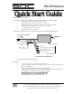
SG-235 Manual Quick Start Guide Remote Manual Tuning To quickly install your antenna coupler you will need the following: 1. An HF radio installation with 3 to 500 watts output. 2. An HF antenna with a single wire feed (not coax fed). Minimum length of 50 feet (from 3.0 MHz) or 300 feet (from 1.8 MHz). 3. A good ground (counterpoise) for the antenna and coupler 4. +12 VDC and ground for the coupler. 5.
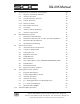
SG-235 Manual Table of Contents 1.0 2.0 3.0 4.0 5.0 General information 8 1.1 Experience Levels of Users 8 1.2 What is an Antenna Coupler? 8 1.3 Overall Description 10 1.4 Coupler Network Configuration 11S 1.5 Operation Indicators 11 1.6 Mechanical Configuration 12 1.6.1 Marine Installation 12 1.6.2 Desert and High Temperature Mounting 13 1.6.3 Extremely Cold Temperatures 13 1.7 Remote Installations 14 1.8 Upgrade Sequences 15 Specifications - SG-235 16 2.
SG-235 Manual 6.0 7.0 8.0 9.0 10.0 6 © 1998 SGC Inc General Notes on Antennas and Couplers 34 6.1 Steps to Antenna Installation 36 6.2 Antenna Location 36 6.3 Ground Systems - General 38 6.3.1 Vehicle Grounds 38 6.3.2 Marine Grounds 38 6.3.3 Base Station Grounds 39 6.4 Corrosion 40 6.5 Antenna Tuner Mounting 41 6.6 Antenna Connection 41 Installation Procedures 42 7.1 Installation with SG-2000 42 7.2 Installation with SG-500 or other 500-watt amplifiers 43 7.
SG-235 Manual 11.0 10.1 Tune, Tune Lock, and Reset 61 10.2 Smartlock PRO Notes 61 Quick Start Guide - Remote Manual Tuning 62 Troubleshooting the SG-235 - General 63 11.1 Ground Faults 63 11.2 Antenna Faults 64 11.3 Transmitter Faults 66 11.4 A Final Pointer on Troubleshooting 67 Warranty Information 68 Schematics Appendix - QMS System QMS Brochure SG-500 SmartPowerCube Brochure SGC Inc. SGC Building, 13737 S.E. 26th St. Bellevue, WA 98005 USA P.O.
SG-235 Manual 1.0 General Information The Smartunerª reputation has grown to legend status because it is simple to use and highly reliable. A Smartuner will provide maximum transfer of radio energy from any HF transmitter to any end-fed HF antenna within the frequency and power limits of its specifications. The SG-235 is a high-powered cousin of the SG-230PRO.
SG-235 Manual ¥ A tuner placed at the transmitter loads up the feedline as well as the antenna (so that the feedline radiates). ¥ A coupler installed at the antenna eliminates feed line losses by providing a proper match of the antenna to the feed line. The Smartuner is a true antenna coupler. We will emphasize these key points throughout this manual to yield the best possible operation of your Smartuner. These include: ¥ The coupler must be located at the antenna.
SG-235 Manual 1.3 Overall Description The SG-235 is a general purpose coupler which can operate with any type of HF radio and almost any type of antenna configuration. The coupler network configuration is of a ¹ or L type; sensors continually monitor the state of the tuning and relay this information to the processor. Tune. The initial (first time) tuning may take several milliseconds to a few seconds depending on the complexity of the tuning process for a specific antenna configuration.
SG-235 Manual If broadband operation is required during scanning operations, jumper JP-2 on the printed circuit board inside the coupler may be set to the ÒYESÓ mode. This will bypass tuning elements on Receive. Jumper JP-2 is located adjacent to the shield along the edge of the printed circuit board. In some cases, it may be desirable to re-tune the coupler and bypass the memory information. If you wish to bypass the recalled tuning solutions, place jumper JP-1, also located near U2, to the ÒNOÓ position.
SG-235 Manual CAUTION: Dangerous high voltages exist inside the Smartuner when it is operated with an HF transmitter. High RF voltages in excess of 10 kv may be expected in normal operation of this unit. In addition to shock hazard, these RF voltages may produce burns which are very painful if you come in contact with exposed components. Therefore, DO NOT operate without the cover secured in place unless you are a well experienced radio technician or engineer.
SG-235 Manual protective housing is recommended. The preferred installation if vertical is with the standoff insulator pointing upward. A stuffing gland for the RF and DC cables is provided on the lower edge of the weather housing, along with a 1/4-20 stainless steel ground stud. The antenna connects to the ceramic insulator on top of the weather housing. The SG-235 may be mounted in any position, including inverted, without any degradation of performance.
SG-235 Manual 1.7 Remote Installations The SG-235 is supplied with a standard 25 feet of cable. If necessary, the coupler can be installed up to 100 feet from the transmetter. However, SGC does not recommend installing the Smartuner more than 100 feet from the transmitter because two losses must be considered. ¥ The first loss in long distance installations is normal attenuation of the radio signal coming from the transmitter to the antenna via the coax.
SG-235 Manual 1.8 Upgrade Sequence The current version of the SG-235 coupler will have a revision letter located on the printed circuit board. To continue moving forward in coupler design, the SG-235 may be revised as needed. Later revisions of the coupler will be denoted by the subsequent letters of the alphabet. The SG-235 contains all the latest revisions of the standard SG-230PRO to ensure the user is acquiring all the benefits of the SG-230PRO along with the added benefits of the SG-235.
SG-235 Manual 2.0 Specifications - SG-235 HF Frequency Range: 1.8 to 30.0 MHz Note: The SG-235 may be operated as low as 1.6 MHz and is commonly used as an antenna matching unit for differential GPS transmitter site antennas. However, when operated under these conditions, a longer antenna is recommended, such as a 360 foot tower section for operation in the 1700-1710 kHz band and an appropriately larger counterpoise.
SG-235 Manual 3.0 P ar t s F u r nished (u np ack ing ) Antenna Coupler 25 foot special cable (RG-58 plus 12 conductors in a single jacket) Instruction Manual SmartLock PRO coupler controller with 25 foot cable. 3.1 User Supplied Items The user of the SG-235 will need to supply a suitable HF radio antenna. Such an antenna may be as simple as an 23 foot long piece of wire and several ground/counterpoise radials of 23 feet or longer.
SG-235 Manual detail. If you are dealing with a marine installation, you should have a description of the vessel's bonding system. If you are using the coupler in a mobile setting, you should be able to describe bonding of the hood, trunk and other vehicle parts which may have been done. In an aircraft, you should be able to describe the location of the coupler and the type of ground connection used.
SG-235 Manual 4.0 Antenna Types R e co m m e n d e d A n t e n n a s SG-105 - Marine and Base station antenna. This is a 60-foot end-fed long wire type antenna. SGC Part Number 55-10. SG-114 - Base station antenna. 200 feet SGC Part Number 55-14 SG-203 - Marine 28-foot whip antenna. This antenna is used for most power boat installations. SGC Part Number 55-23. SG-303 - High performance 9-foot whip antenna. This dual element antenna is designed for severe marine and land mobile service.
SG-235 Manual a conventional Vee antenna as an inverted Vee. The coupler is very flexible in this regard. 4.1 Antenna Selection The automatic antenna tuner will operate into almost any end fed antenna with a length of 2.5 meters or more, provided an effective ground is used. The antenna efficiency will be proportional to length and in most applications will be maximum at a length of 1/4 wavelength. This means that the longest possible antenna should be selected for each installation.
SG-235 Manual Antenna Length vs. Lowest Tunable Frequency Antenna Length in Feet (approximate) 4.6 Lowest Frequency in KHz 350 feet 1650 KHz 335 feet 1700 KHz 315 feet 1800 KHz 285 feet 1900 KHz 275 feet 1950 KHz 220 feet 2000 KHz 100 feet 2500 KHz 50 feet 3000 KHz Backstay Antennas 8 meters (28 ft) and longer Although we would love to sell everyone a high performance marine whip antenna, the backstay of a sailboat is almost impossible to improve upon in most installations. SGC Inc.
SG-235 Manual 5.0 Typical Installations Figures 5.01 through 5.3.1 show some typical installations for the automatic antenna tuner. Figure 5.01 Jeep Installation SG-303 whip 2.0 M whip Jeep Installation for Automatic Antenna Coupler Detail Transceiver Coupler Feed-through insulator Figure 5.02 GTO cable (as short as possible) Vehicle installation Ground coupler securely to truck SG-303 2.0 M whipwhip Feed through insulator Coupler Transceiver Vehicle Installation 22 © 1998 SGC Inc SGC Inc.
SG-235 Manual Figure 5.03 Motor Vessel installation Feed through insulator Coupler Suitable stay cable Ground to steel bulkhead or overhead Motor Vessel Installation Figure 5.04 Base installation 7M to 10M GROUND LEAD 1.5M MAX GROUND ROD (3M) SGC Inc. SGC Building, 13737 S.E. 26th St. Bellevue, WA 98005 USA P.O. Box 3526, 98009 Fax: 425-746-6384 Tel: 425- 746-6310 or 1-800-259 7331 E-mail: sgc@sgcworld.com Web site: http://www.sgcworld.
SG-235 Manual Figure 5.05 Base installation with ground wire radials pole or tree supports far end Insulator 11M 2M 30° Insulator GTO cable 30° Coupler 2M Radial wires buried in soil Ground cable No. 4 AWG (150 cm maximum) Base Installation with Ground Wire Radials Conduit for control cable and coax Figure 5.
SG-235 Manual Figure 5.07 Base Quadra Loop Horizontal Radiation Porcelain isolators with tie rope Coupler Ground bolt terminal 50 ohm coax from transmitter Antenna terminal Base Quadra Loop Horizontal The horizontal quad loop is a groundless antenna for high angle radiation and is ideal for HF communications from zero to 500 miles in the frequency range of 2 to 10 MHz. This configuration provides optimum near-right angle reflection to the ionosphere for short range communications.
SG-235 Manual up to 300 feet up to 200 feet Balanced Line Feeders 300-600 Ohms GND Figure 5.08 Base Ladder Installation Hot Coupler RF cable Control cable Base Ladder Installation Figu re 5.09 Base Delta L oop The delta loop antennas are ideally suited to long range communications due to their low angle. This configuration is Radiation best for communications ranging from 500 to 5000 miles in the HF frequency range of 4 to 22 MHz. Noise rejection is excellent, as stated for the quad loop antenna.
SG-235 Manual Figure 5.10 Vessel Groundless Loop Radiation 75 feet Vessel Groundless Loop Co u p l e r Porcelain isolator Lower mast connection to coupler RF ground The triangular loop antenna for sailboats is designed to operate in a groundless environment and still provide high performance. This type of installation will require only one insulator point on the bottom backstay and an electrical connection on top of the mast and stay.
SG-235 Manual The insulated backstay antenna requires two porcelains isolators. The coupler must be placed as close as possible to the base of the backstay antenna. Proper grounding of the coupler is very important. Connect the RF ground terminal of the coupler to all metal parts or structures of the boat (keel, engine, etc.). 5.1 APARTMENT LOOP ANTENNA Loop antennas can be used very effectively in small apartments, offices and holding rooms.
SG-235 Manual achieved with the loop mounted vertically. The vertical loop antenna of one quarter wavelength is the basis of the "quad" type directional antenna. Figure 5.12 Small loop antenna (3 x 4 feet) Pegs or Nails Use 6-8 turns of #16 or larger wire which is insulated for high voltages. No spacing between turns. Use a total of 70-90 feet of wire.
SG-235 Manual An End fed antenna could be very effectively used if a metal cabin structure is available. Loop antennas have the advantage of not requiring a ground system, but are highly directive. Mounting the antenna is relatively simple and can be mounted on short (18 inches 1/2 inch diameter) plastic plumbing pipes. In the end fed antenna, it is recommended that the antenna be as long as possible in an "L" shape configuration, as illustrated in the following diagram. 5.
SG-235 Manual When installed in high performance turboprop or jet aircraft, the Smartuner will operate well with a shunt fed antenna. This is generally a 13 foot piece of metal which mounts on the fuselage of the aircraft and is grounded to the aircraft at one end. The device looks something like a towel bar on the underside of the aircraft.
SG-235 Manual to secure the joints with hose clamps or plumbers tape to assure low resistance connections. C. Masonry chimneys are visually "busy". You can run a #10 copper wire parallel to the chimney with little risk of detection. Some short stand offs and you have a support for a vertical dipole type antenna. B C COUPLER COUPLER D COUPLER D. The Inverted "L" antenna may work slightly better if it is installed clear of a building, but for covert operations, this type of installation is a favorite.
SG-235 Manual antenna and a strongly built (Mylar or nylon) kite. Remember that when a mast comes down, you have easy access to the high voltage feedline which may be secured to a kite antenna. Offshore power boats can use this antenna as well, since 10-20 knot winds are almost always available when underway at sea. 5.5.
SG-235 Manual 5. Strung between rooftops of buildings. 6. Sign posts such as for banks and gasoline stations. 7. Telephone (not power) poles. There's no line noise on telephone poles. 8. Railroad trestles 9. Highway structures - signs, overpasses and bridges. 10. Flag poles at public buildings, schools and hospitals. 5.9 TACTICAL Grounds and counterpoises Just as antenna opportunities abound, so do ground and counterpoise opportunities to the professional eye.
SG-235 Manual expected in your radiation or receiving characteristics. This is the equivalent of transmitting with 400 watts, when in actuality you are using only 100 watts. 2. A ground for "end fed" antennas can be very effectively created by running radial wires from the coupler point and laying them onto the ground. It is recommended that for a good ground, 12 radials should be used and they be about 1/3 larger than the antenna length.
SG-235 Manual SG-235 coupler is specifically designed to be used for such applications. 9. For vehicular installation, do not use any inexpensive CB antennas and/or mounts. These antennas will not perform well between 1.8 to 10 MHz even though the coupler will load and tune the antenna whip. A very high voltage of 15 to 30,000 volts RF will be applied to the antenna depending on the RF power level and frequency. The inexpensive ball mounts for CB antennas are not designed for this stringent a purpose.
SG-235 Manual 2. The antenna should be kept as far away as possible from buildings, trees and vegetation. If metallic masts or supports are used, arrange the insulators so the antenna is spaced at least 2 meters from the mast. 3. Remember that the radiating part of the antenna starts at the tuner. The location of the bottom portion of the antenna is very important. 4. Vertical antennas have an omni-directional radiation pattern and will provide equal performance in all directions. 5.
SG-235 Manual 6.3 Ground Systems - General The ground system (also called a counterpoise) is a key part of the overall antenna system and is the primary cause of poor performance and the difficulty of adjusting the tuner. A good ground is essential. 6.3.1 Vehicle Grounds Connect the tuner directly to the frame of the vehicle. Ensure that a heavy strap is used from the tuner ground lug and that the connections are cleared of all paint and dirt so that the shiny metal is exposed.
SG-235 Manual In a and just and sailboat installation, we generally place the Smartuner in the aft lazarette then run at least three runs of foil forward. One runs up the port chine, below the waterline, another up the starboard chine below the waterline the third up the center of the vessel. The center foil is generally connected to the rudder post, transmission, engine and keel bolts. The chine foils are attached to through hulls, the stove, tankage and so forth.
SG-235 Manual and should be installed as close as possible to the tuner. It may be necessary to use several ground rods bonded together to improve the ground contact. Water pipes are sometimes recommended as grounds and may be used provided plastic pipe is not buried as part of the system and the following conditions are met: a) The water pipe is close to the tuner. b) The water pipe enters the ground very close to the tuner bonding point.
SG-235 Manual Use jumpers around metal backstay triangles on split backstay antennas. Corrosion may cause up to several hundred ohms of resistance to occur even though you may think that a metal-to-metal connection would be a good one. 6.5 Antenna Coupler Mounting The coupler is mounted using the proper mounting ears on the case. Choose a location immediately adjacent to the antenna feed point.
SG-235 Manual 7.0 Installation Procedures The following diagrams will assist in installing the Smartuner with SGC equipment. 7.1 Installation with SG-2000 The SG-2000 is shipped with all necessary connectors for installation of a Smartunerª and for installation of peripherals via the audio input/output jack on the rear panel. You will see the connectors when you remove the Phillips head screws which hold the protective sheet metal cover over the rear panel connectors.
SG-235 Manual On All Radios: The SG-235 requires only a source of 13.6 VDC, an RF transmission line (RG58/U up to 30 ft., RG-8 OR RG-213/U if over 30 ft.) plus suitable ground and antenna systems. No band switch information, low power tuning or handshake is required, since the coupler tunes on RF voice or carrier. Power consumption is normally less than 1 amp, allowing for use of small gauge wire. The fully PCB is protected against power reversal.
SG-235 Manual Connections: SmartLock Pro to SG-235 Smartuner Red Ñ Red wire (+12 VDC) Green Ñ Green wire (Remote tuned indicator line) White Ñ White wire (Hold Settings) Blue Ñ Blue wire (Reset) Black Ñ Black/Yellow (Ground) We recommend soldering the wires together and insulating the exposed wires with heat shrink or electrical tape. Other methods may suffice as long as the connections are firm and no wiring remains exposed.
SG-235 Manual 7.4 WEATHERDECK MOUNTING Weatherdeck mounting can be used. Years of experience have shown that inside mounting or even splash-proof mounting is preferred, particularly in cold, damp environments. In tropical use, shielding from direct sunlight is desirable. The base of the antenna should be connected to the high voltage feed-through insulator on the housing. (Note: this insulator is not designed to support heavy mechanical loads.
SG-235 Manual Note: When changing to a new frequency, the SG-235 has a 4 second time delay before it will initiate a retune cycle. This can be bypassed by connecting Brown wire (PTT IN) to your radio external PTT output.
SG-235 Manual 8.1 Alternate Electrical Checkout On Site Radio HF/SSB Transmitter & Coupler Test Procedure Light bulb test. If you suspect that there is a problem with your transmitting equipment, here is a simple test that you can perform to find out if your station equipment is operating properly.
SG-235 Manual 6 - If the coupler operates as described above, it is almost certain that it will give satisfactory service with a proper antenna. If you are still having trouble, we hope that you will contact us for a free copy of our HF SSB User's Guide and Products Catalog which contains much additional information. If the lamp does not light: (be sure light bulb is good) 1 - Make sure that the radio is set to the CW mode.
SG-235 Manual A light bulb connected to the antenna jack of a radio is simple and effective method to test if your radio is transmitting. The instruction below explain how to test the SG-2000 HF Radio and optionally the SG-235 Coupler. This test can be modified and adapted to work on any other radio. Equipment Required: SG-2000 Radio or any HF SSB and AM/FM Transmitters.
SG-235 Manual 8. Set power to HI 9. Set the radio to AM mode or CW and any carrier. 10. Key "push to talk" switch on microphone, and observe the light bulb. The light should come on if the radio is transmitting. Observe that the light is not as bright as step 5. 11. Set the radio to SSB mode 12. Key "push to talk" switch on microphone and talk into the microphone. Observe the light bulb comes on when you talk. RF GND RF IN-OUT SG-2000 Radio Coupler Test Procedure: 1.
SG-235 Manual Coupler Test Procedure Continued N o t e : The light bulb may not come on immediately if the coupler has not yet been tune for that frequency. The light bulb brightness is greatest when the coupler is tuned for that frequency. RF GND Antenna Jack RF IN-OUT SG-230 Antenna Coupler GND SG-2000 Radio 8.2 COUPLER CONFIGURATION Schematic Q30102500, sheets 1 and 2, are the schematic diagrams of the antenna coupler. RF input is applied through connector J5; +13.
SG-235 Manual network, eight inductors in the series arm, and five more capacitors in shunt on the output arm, all arranged in binary increments. Relays are provided in conjunction with each lumped constant and allow removal or entry as desired. A network having 64 values on input shunt C, 32 values of output shunt C, and up to 256 values of series L is possible with the manipulation of these 38 relays. 8.
SG-235 Manual pler as noted from the generator. A line current sample is compared in phase with a voltage sample in a double balanced mixer. Output polarity is positive for a net capacitive reactance. The output of the phase detector A1 is shifted to a 0 to 5V range, then fed to the processorÕs A to D converter ports and used within the microcontroller. 8.
SG-235 Manual 8.9 INFORMATION READ The data sensors are interfaced with the CPU through input ports PA3 through PA7. After an IRQ, the tune algorithm program can access any desired variable by simply searching for the desired input port (lacking any applicable pre-stored data). Since the comparators effectively preprocess the desired data, to read any specific variable, the CPU need only look at the required port for the desired variable. 8.
SG-235 Manual SG-235 MicroTun e ª Software Copyright November-1991 9.0 Tuning Process and Options The SG-235 MicroTuneª Software is unique software which allows fine and precise tuning of the digitally controlled ¹ & L network antenna coupler configurations. Antenna L1 50 ohms C in C out The versatile MicroTuneª software offers its' user these special functions: ¥ The coupler is activated whenever forward power is present.
SG-235 Manual ¥ Facilities and algorithms are used, which enable accurate tuning at the low end of the frequency band, and the use of even shorter antennas than previously possible. ¥ The BITE (Built-In-Test-Equipment) Indicator Tune LED includes a safety feature which alerts the operator to a mismatched condition, via blinking indicators, when proper tuning conditions have not been met.
SG-235 Manual The recalled data is then tested for validity. If the data proves invalid, it is bypassed and re-tuning is performed. If the data recalled proves valid, the data is sent to the relays and the VSWR is checked. If the VSWR is less than 2:1, the program branches to the "OK Tuned" section of the program. If the VSWR is found to be greater than 2:1, the program branches to the "re-tune" program. Several tests are made to determine which tuning algorithm or path should be used to tune the coupler.
SG-235 Manual tests and appropriate subroutines are executed throughout the tuning process. Following are examples of the activity that occurs when the tuner must be matched to a frequency that requires a slightly longer or shorter antenna: 9.3 Antenna Too Short Antenna L1 50 ohms C in Once the tuner has verified RF power, the tuning sequence is as follows: 1. Series inductance is added until the phase is deemed as being inductive. At this point it is normal for the input impedance to be low. 2.
SG-235 Manual 9.4 Antenna too long Antenna L1 50 ohms C out Once the tuner has verified RF power, the tuning sequence is as follows: 1. Output capacitance is added until input impedance test results are low. 2. At this point, the antenna will be capacitive. Therefore, series inductance is added until the antenna is no longer capacitive. 3. Fine tuning is performed by trying a small amount of input capacitance (this may or may not be required). 4.
SG-235 Manual If typical operation is out of band duplex, '"YES'" would be most likely to give better performance. If in band operation is typical and duplex or simplex is the predominant mode of operation, then 'NO' is usually the better choice. 9.6 J-1 - Tune from memory (FACTORY default SETTING: YES) YES In this position the tuner will recall data previously saved and try this data before attempting to re-tune. If the data is valid and the VSWR is less than 2:1 the tuner is done.
SG-235 Manual 9.7 J P 3 - P T T out Control ( F a c t o r y d e f a u l t s e t t i n g : Y E S) Y E S In this position, the SG-235 will keep the 500-watt amplifier in the transmit mode (after the coupler has found a match) as long as the PTT signal from the radio is asserted (low), whether or not RF power is applied to the coupler.
SG-235 Manual and store the new setting in memory, over writing any previous settings. To return to normal Tune From Memory, simply push the reset button while in Normal Position. Quick Start Guide Remote Manual Tuning To quickly install your antenna coupler you will need the following: 1. An HF radio with 3 to 500 watts output. 2. An HF antenna with a single wire feed (not coax fed). Minimum length of 50 feet (from 3.0 MHz) or 300 feet (from 1.8 MHz). 3.
SG-235 Manual 11.0 Troubleshooting the SG-235 Only a small number of installation mistakes can be made. These will fall into one of several categories: ground fault, cable fault, and antenna fault. There is also a slight chance of an electrical fault in the coupler. When you are troubleshooting the SG-235 and you understand that there are three variables, you should change each variable, in sequence, to determine where the problem lies.
SG-235 Manual By the way, this is why we don't like to use aluminum ground wires as radials. Just as when aluminum is used in house wiring, several gauges larger are needed to carry the same amount of current the same need applies here. I m p r o p e r b o n d i n g . The fourth kind of ground fault you may encounter occurs where the ground is not properly bonded to the coupler. We go to considerable effort to make sure the stainless steel ground stud is well connected to the coupler.
SG-235 Manual In working through the logical troubleshooting process with him, we discovered that he had used coaxial feed line from the insulator on the coupler to the antenna feed point. Because he had read about the dangers of capacitance to ground in an earlier edition of this manual, he did not have the coax shield grounded. We had him remove the ungrounded braid and the installation worked fine.
SG-235 Manual money by expecting the fiberglass hull to act as an insulator and not using a lower insulator. The hull is not a good insulator and a thin layer of wet salt water will degrade the ground further. Similarly, mobile HF users who rely on a poor quality ballmount find these are especially prone to arc over inside the ball mount where it is difficult to detect.
SG-235 Manual 11.4 A Final Pointer on Troubleshooting Remember that the SG-235 is an excellent piece of equipment which will give outstanding performance. If you have a problem with the coupler finding a tuning solution, you should change one variable at a time. SGC Inc. SGC Building, 13737 S.E. 26th St. Bellevue, WA 98005 USA P.O. Box 3526, 98009 Fax: 425-746-6384 Tel: 425- 746-6310 or 1-800-259 7331 E-mail: sgc@sgcworld.com Web site: http://www.sgcworld.
SG-235 Manual SGC Equipment Standard Warranty SGC wishes you to be satisfied with your new equipment purchase. This SGC product therefore is warranted to be without defect in workmanship or materials for a period of one year from the date of purchase. Proof of a date of purchase is required when requesting warranty service.
SG-235 Manual Notes SGC Inc. SGC Building, 13737 S.E. 26th St. Bellevue, WA 98005 USA P.O. Box 3526, 98009 Fax: 425-746-6384 Tel: 425- 746-6310 or 1-800-259 7331 E-mail: sgc@sgcworld.com Web site: http://www.sgcworld.
Appendix - QMS System AppendixÑ QMS System Introduction SGCÕs QMS (Quick Mount System) is the newest addition to the many outstanding products manufactured by SGC, Inc. that incorporate the latest technological developments in both design and craftsmanship. Featuring state of the art technology in microprocessor-based communication equipment, the QMS represents high reliability backed by over 28 years of communication experience. NOTE: SGC, Inc.
Appendix - QMS System 3. If you will be traveling in an area where overhead restrictions may prevent use of your SG-303 antenna, the antenna should be folded down and secured to prevent damage from brush, trees, or low structures.
Appendix - QMS System 4. When connecting the coupler to the radio/transceiver, a passageway for the control cable (consisting of an RG-58 coax cable, control wire, power, and ground, plus the optional tuned indicator wire) will need to be provided. Note: By removing the four screws for the ratchet mount base of the SG-303 antenna, the mount can be installed or reinstalled to provide the user with the set-up most suitable for the application. Insure the screws are tightly secured after reinstallation. 5.
Appendix - QMS System SHEETS OF PAPER WILL PREVENT SUCTION CUPS FROM BECOMING RE-ATTACHED DURING PLACEMENT OR REMOVAL 8 FT.
Appendix - QMS System 2. Insure that the high voltage wire protruding from your antenna system is not routed near any metallic objects such as your vehicleÕs frame or metal posts. This wire is part of the flexible insulator of your QMS system. 3. Insure that the ground braid is attached to a good vehicle ground system. Do not run ground currents through any hinges. Be sure to make the ground braid as short as possible. Remove all paint and rust from your grounding area.
Appendix - QMS System WARNING: If you do not properly and securely attach this unit to the vehicle and it comes loose, the speed of the vehicle may cause the unit to injure others. General Installation Information The mobile communication tips found below apply to any mobile installation, not merely to the QMS or other SGC product. ¥ For the best performance and radiation, always mount your antenna system on the highest part of the vehicle.
Appendix - QMS System Use of the gel cell battery may require a lesser gauge wire to recharge, in comparison to the large wire required to connect the radio directly to the main battery. ¥ In the charging line of this auxiliary battery, you may want a diode of 100 Amp. capacity to allow the battery to be charged, so as not to discharge with the rest of the electrical system. (You could use this auxiliary battery, in an emergency situation, to jump the main battery.
Appendix - QMS System Figure A-4ÑSuction Cup (underside view) Apply silicon grease to shaded area This will prevent slow leakage of air, which will reduce the holding power of the suction cups over time. It will also protect the painted surface. If the surface of the vehicle is very rough, the installation procedure remains the same. The suction cup will have to be pressed against the vehicle surface in the same way, but more lubricant may be necessary. T i g h t e n i n g t h e Q M S S t r a p s .
Appendix - QMS System ¥ To make removal of the unit easier, you may slide a piece of paper between the suction cup and the vehicle surface (see Figure A-3). In this way, each of the suction cup tabs may be loosened sequentially as shown: S t o r i n g Y o u r Q M S . To store your QMS unit for long periods of time, apply a thin coating of talcum powder to the suction cups. This treatment increases the life span of rubber products. SGC Inc. SGC Building, 13737 S.E. 26th St. Bellevue, WA 98005 USA P.O.
Q M S Antenna Coupler System The Quick Mount System for any mobile HF rig No Compromise Communications • QMS offers unsurpassed frequency agility needing no user intervention • QMS includes SGC Smartuner automatic antenna coupler, extended full-range antenna, and weather resistant QMS package QMS Descriptions: QMS-b2 cat. #55-47 includes the SG-230 (200W) 1.8 to 30 MHz SG-303 9 ft. antenna QMS-b3 cat. #55-48 includes the SG-235 (500W) 3.0 to 30 MHz SG-303 9 ft. antenna QMS-a7 cat.
The QMS Antenna System S Specifications: (QMS-7 specifications included on separate brochure.) trap the QMS on your favorite family or business vehicle. You’ll find it gives any HF-SSB superior frequency agility and exceptional performance. The SGC Smartuner automatic antenna coupler, the SG-303 extended full-range antenna, and the special exterior QMS mounting package comprise the QMS. Mounting coupler and antenna outside the vehicle reduces engine noise and interference.
SG-500 SMARTPOWERCUBE Microprocessor Controlled Linear Amplifier TM (cat. #52-96) Dramatically boost your which has occurred. Backing up this userpower, at low cost. fault friendly visual system, the SG-500’s microprocessor protects the SmartPowerCube from faults with preprogrammed shutdown procedures; in the event of a microprocessor fault, the unit shuts down automatically. The SG-500 is designed to do exceptional service in fixed, mobile, and marine applications.
SG-500 SmartPowerCube TM Power Output: SSB: CW: Full 500 watt output. • The SG-500 produces enough power to be within 1 “S” unit (3dB) of a 1 kW amplifier. Microprocessor Controlled: • Automatically adjusts amplifier input sensitivity. • Monitors all parameters for faults (Heat, high VSWR, under voltage, etc.). • Automatically selects the correct filter band. • Export versions control transmit/receive switching. Heavy duty cooling fan option for continuous CW use. (cat.
© Augus 1998 SGC nc e@@e?@3?e@?e?@ ?@e?5@@@@@@@@@@@@2?6@@@@@@X)@3?h@?g?1@Ne1V @? @?e?@e?@@?e@@e?@@?e@?e?@ ?@e?@@?eK)@@@@@?g@@7?L@@? ?L@3eL3 @ e??@@e e??@@@@??e e@@@@e e??@@f 7?e@@??e ??@@e ???@@@@?@h @? ? @@??e e??@@ e??@@@@??e e??LH@@@@@?@@@7??g g@@@@Je @@g@@?@+@V3g g@@@7e eH)@@@@ @? @?e?@e?@@?e@@e?@3?e@?e?@ ?@e?@@?e?5@@?@h@@e?@@@@@g@@@@f)@@?eX6@@ @ @ ??@@e ?1@@@@@?@@3@??e @ @? ? @? ?e e? ?@@e e??@@@@??e e@@@@e e??@@@@??e e@@??e e??@@ e??@@@@??e f eY50@4@V@@@@@e e??@@@@@?@h @?0@fX?)L@@3@ @? @?e?@e?@@?e@@e
SG-235 500 watt Smartuner ™ Automatic Antenna Coupler for all HF-SSB Bands and Modes Smart Tuning—Now at 500 watts . Now you can achieve perfect coupling of your 500-watt HF-SSB to your antenna. Now you can go mobile at 500 watts. The SG-235 Smartuner™ forms the perfect link with any 500-watt amplifier for high power performance.