
User`s guide


14 SGI
®
Altix
®
XE210 User’s Guide
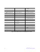
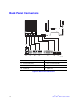
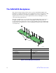
Front of Server System
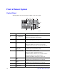
Control Panel
The diagram below shows the features available on the control panel..
Callout Feature Function
A.
B.
NIC 2 Activity LED
NIC 1 Activity LED
Continuous green light indicates a link between the system and
the network to which it is connected.
Blinking green light indicates network activity.
C. Power/Sleep Button Powers on/off the system.
Puts the system in an ACPI sleep state.
D. Power/Sleep LED Continuous green light indicates the system has power applied to
it.
Blinking green indicates the system is in S1 sleep state.
No light indicates the power is off / is in ACPI S4 or S5 state.
E. Hard Disk Drive
Activity LED
Random blinking green light indicates hard disk drive activity.
No light indicates no hard disk drive activity.
F. System Status LED Solid green indicates normal operation.
Blinking green indicates degraded performance.
Solid amber indicates a critical or non-recoverable condition.
Blinking amber indicates a non-critical condition.
No light indicates POST is running or the system is off.
G. System Identification
LED
Solid blue indicates system identification is active.
No light indicates system identification is not activated.
H. System Identification
Button
Solid blue indicates system identification is active.
No light indicates system identification is not activated.
I. Reset Button Reboots and initializes the system.
J. USB 2.0 Port Allows you to attach a USB component to the front of the chassis.
TP02160
L JK
H
I
BA F GEDC