
User`s guide


Front and Rear Panel Components
007-5717-001 11
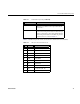
Table 1-4 describes the pinouts for the serial connector when Roamer is not installed.
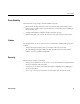
Rear fans Keep the area behind the fans clear and unobstructed. This
will ensure proper airflow to the components inside the
server chassis.
Serial connector This port is accessed with an RJ-45 connector. When the
Roamer remote management module is installed, this port
functions as an interface to the module. When the Roamer
remote management module is not installed, the pinout for
the serial connector is as shown in Table 1-4.
Table 1-4 Pinouts for the Serial Connector J3
Pin Name Description
1 RTS Request To Send (JP1 “A”)
CTS Clear To Send (JP1 “B”)
2 DSR Data Set Ready
3RxD Receive Data
4 GND Ground Return
5 GND Ground Return
6 TxD Transmit Data
7 DTR Data Terminal Ready
8 CTS Clear To Send (JP1 “B”)
RTS Request To Send (JP1 “B”)
Table 1-3 Front Panel Components (continued)
Component Description