
Product Info


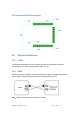


Table Of Contents

©Ehong Technology Co.,Ltd Page 13 of 14
12. Layout and Soldering
12.1
Layout
• Module power supply: 3v button battery or DC 3.3v
• Power pin connection capacitor is as close as possible to chip and pin
• Decoupling the power supply from the chip using a capacitor
• Use capacitors to prevent noise from coupling back to the power plane.
12.2
Layout Guidelines
To optimize antenna performance, place the module in the corner of the PCB as
shown in Figure 6. Do not cover copper and trace the antenna clearance area. Keep
the antenna area as far away as possible from the power supply and metal
components. Connect all GND pins directly to a solid GND plane. Place GND vias as
close as possible to the GND pin. Use a good layout method to avoid excessive
noise coupling with signal lines or supply voltage lines
13. Development Kit
Note: For the use of development boards and kits, please refer to Ehong Development
Board datesheets.