)&& ,' 6< $ CHCNAV i73 GNSS USER GUIDE Revision 1.
Table of Content Table of Content Table of Content............................................................................................................... 2 Preface ............................................................................................................................ 5 Copyright ........................................................................................................................... 5 Safety Warnings ............................................................
Table of Content 3 Equipment Setup and Operation .............................................................................. 24 3.1 Post-processing Base Station Setup ........................................................................... 24 3.2 Real-Time Rover Station Setup .................................................................................. 26 3.3 Working with the Tilt Compensation......................................................................... 27 3.3.1 Operation Steps ....
Table of Content 5.7.1 Firmware Info Submenu ................................................................................. 63 5.7.2 Hardware Version Submenu ........................................................................... 63 5.7.3 Config File Submenu ....................................................................................... 63 5.7.4 System Log Download Submenu .................................................................... 64 5.7.5 User Log Submenu .........................
Preface Preface Copyright Copyright 2018-2020 CHCNAV | Shanghai Huace Navigation Technology Ltd. All rights reserved. The CHCNAV is trademark of Shanghai Huace Navigation Technology Limited. All other trademarks are the property of their respective owners. Trademarks All product and brand names mentioned in this publication are trademarks of their respective holders. Safety Warnings The Global Positioning System (GPS) is operated by the U.S.
Preface CE Interference Statement Declaration of Conformity: Hereby, Shanghai Huace Navigation Technology Ltd. declares that this i73 is in compliance with the essential requirements and other relevant provisions of Directive 2014/53/EU. A copy of the Declaration of conformity can be found at Shanghai Huace Navigation Technology Ltd.
Introduction 1 Introduction The i73 GNSS receiver removes barriers to portability without sacrificing performance. Featuring full GNSS technology, it offers best-in-class GNSS signal tracking even in a harsh environment, enabling GNSS surveying beyond usual constraints. The i73 GNSS incorporates the latest innovations such as an inertial module (IMU) providing automatic pole-tilt compensation in a very compact design. 1.1 Safety Information 1.1.
Introduction 1.2.1 Use and Care This receiver is designed to withstand the rough environment that typically occurs in the field. However, the receiver is high-precision electronic equipment and should be treated with reasonable care. CAUTION - Operating or storing the receiver outside the specified temperature range will cause irreversible damage. 1.3 Technical Support If you have a problem and cannot find the information you need in this manual or CHCNAV website (www.chcnav.
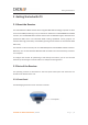
Getting Started with i73 2 Getting Started with i73 2.1 About the Receiver The new CHCNAV i73 GNSS receiver offers integrated IMU-RTK technology to provide a robust and accurate GNSS positioning in any circumstances. Unlike the standard MEMS based GNSS receivers, the i73 GNSS IMU-RTK combines state-of-the-art GNSS RTK engine, calibration-free professional IMU sensor and advanced GNSS tracking capabilities.
Getting Started with i73 The front panel contains four indicator LEDs and two buttons. Satellite LED Correction LED Power button Function button Name Correction LED (Green) Description x Indicates whether the receiver is transmitting/receiving differential data. x The green LED flashes once per second when As a Base station: successfully transmitting differential data. As a Rover station: successfully receiving differential data from Base station.
Getting Started with i73 2.2.2 Receiver Ports The receiver ports contain one TNC radio antenna connector, one communication and power ports, one 5/8-11 threaded insert, and one nameplate. TNC radio USB communication antenna connector and power in port 5/8-11 threaded insert Port Name USB Type-C port Description x This port is a USB Type-C connector that supports USB communications. x Users can use USB Type-C Cable supplied with the system to download the logged data to a computer.
Getting Started with i73 2.3 Batteries and Power 2.3.1 Built-in batteries The receiver has two built-in 6800 mAh rechargeable Lithium-ion batteries. 2.3.2 Charging the Battery The rechargeable Lithium-ion battery is supplied partially charged. Charge the battery completely before using it for the first time. Charge via USB Type-C port. WARNING – Charge and use the rechargeable Lithium-ion battery only in strict accordance with the instructions.
Getting Started with i73 2.3.4 External Power Supply Provide the external power to the receiver by the USB Type-C Cable + Power Adapter. The Power Adapter is connecting with AC power of 100-240V, the output port of the Power Adapter connects with the USB Type-C Cable.
Getting Started with i73 2.4 Product Basic Supply Accessories 2.4.1 Rover Kit Basic Supply Item Picture I73 GNSS Receiver UHF Bar Antenna (410-470 MHz) HCE320 USB Type-C Tribrach adaptor 2M Range Pole w/bag Auxiliary H.I. Tool Power Adapter.
Getting Started with i73 2.5 Connecting to an Office Computer The receiver can be connected to an office computer via a HCE320 USB Type-C. Before you connect to the office computer, ensure that the receiver is powered on. The following figure shows how to connect to the computer for serial data transfer or settings: HCE320 USB Type-C 2.6 Connecting to a Controller 2.6.1 Connecting via Wi-Fi with LandStar 7 Software Turn on the controller → run LandStar 7 → go to Config main menu → tap Connect.
Getting Started with i73 Tap the Wireless Lan icon on the right side to select the hot spot → Switch on the WiFi module by the top switch → select the target device in the list. Tap Connect to link to the hot spot. If the first-time connection to this hot spot, user may type in the password.
Getting Started with i73 Tip – The Wi-Fi key of the receiver is 12345678 by default. Tap the Connect button to build the connection. 2.6.2 Connecting via Bluetooth with LandStar 7 Software Turn on the controller → run LandStar 7 → go to Config main menu → tap Connect. In the Connect screen, select CHC for the Manufacture field, i73 for Device Type field, Bluetooth for Connection Type field.
Getting Started with i73 Tap the Bluetooth Manager and turn on the Bluetooth function to search Bluetooth device around → select the target device in the list → Tap back button → select the target device in the Bluetooth manager list. Tap the Connect button to build the connection.
Getting Started with i73 2.7 Downloading Logged Data Data logging involves the collection of GNSS measurement data over a period at a static point or points, and subsequent post-processing of the information to accurately compute baseline information. Data logging using receivers requires access to suitable GNSS post-processing software such as the CHC Geomatics Office (CGO) Software. 2.7.
Getting Started with i73 (4) Double click the folder “repo_receiver SN” (take 3225804 as example), you will see 9 folders. The “push_log” folder is used to save the log files, and the other 8 folders represent different logging sessions and are used for store static data. (5) Double click the folder that you have configured to store the static data, you will see the folder(s) created by the i73 system automatically and named by the date which is decide by GPS time when you start to log data.
Getting Started with i73 (7) Select the data format that you configured to save the static data, you will find the static raw data. Notes: For hcn files, the name of the file is represented as XXXXXXDDDNN, where XXXXXX is the SN of the receiver, DDD is day of year, and NN is the recording session. WARNING – The static data will be saved in the first logging session, the “record_1” folder, by default. Old files will be deleted if the storage space is full.
Getting Started with i73 2.7.2 Web Server Download The procedures of downloading logged data through web server refer to 5.4.4 Data Download Submenu. 2.7.3 USB Download The procedures of downloading logged data in the receiver are as follows: (1) Switch on the receiver and connect it with a computer by HCE320 Type-C. After the successful connection, a removable disk named as the Serial Number (SN) of the receiver will appear on the computer.
Getting Started with i73 (5) Select the destination folder and double click it, and then two folders named as different data format (hcn and rinex) will be displayed. (6) Select the data format that you have configured to save the static data, you will find the static raw data. Tip – For hcn files, the name of the file is represented as XXXXXXDDDNN, where XXXXXX is the SN of the receiver, DDD is day of year, and NN is the recording session.
Equipment Setup and Operation 3 Equipment Setup and Operation 3.
Equipment Setup and Operation No. Name a i73 GNSS receiver b Extension pole (30 cm) c Tribrach adaptor d Tribrach w/ Opti e Aluminum tripod Steps: (1) (2) (3) (4) (5) (6) (7) (8) Put tripod in the target position, center and level it roughly. Place and lock the tribrach in the tripod. Screw the receiver onto the tribrach. Center and level the receiver more precisely. Connect the receiver to external battery by using USB Type-C cable if necessary.
Equipment Setup and Operation 3.2 Real-Time Rover Station Setup For good performance, the following rover station setup guidelines are recommended: Components a b c No. Name a i73 GNSS receiver b UHF whip antenna c 2M range pole w/bag Steps: (1) (2) (3) (4) (5) (6) (7) Connect the UHF whip antenna to the receiver. Screw the receiver onto the pole. Turn on the receiver by pressing the power button for 3 s. Switch on the data controller and connect it to the receiver.
Equipment Setup and Operation 3.3 Working with the Tilt Compensation 3.3.1 Operation Steps (1) Open Landstar7-> Tap PT Survey-> Tap CHCNAV i73 GNSS USER GUIDE | 2020-8 to activate tilt measurement.
Equipment Setup and Operation (2) Shake around according to the procedures in the interface to do initialization. (3) This icon will appear when the initialization is successful. (4) Enter the Name and Antenna, then tap point will be collected and store to Points automatically.
Equipment Setup and Operation (5) When this icon appears, the text will show “Tilt is not available, please measure in alignment” at the bottom of interface. (6) Tap to close tilt compensation. 3.3.2 Notes of using tilt measurement 1. At the beginning of initialization, the pole height of the instrument should be the same as that antenna height in the software. 2.
Equipment Setup and Operation 6. Initialization is required: when the RTK is turned on every time; when IMU module is turned on every time; when receiver drops at working; when the pole is tilted more than 65 degree; when the receiver is stationary more than 10 minutes; when the RTK rotates too fast on the matching pole (2 rounds per second); when the pole hit the ground toughly.
Configuring Through a Web Browser 4 Configuring Through a Web Browser Supported browsers: x Google Chrome x R version 10, or higher Microsoft Internet Explorerƻ To connect to the receiver through a web browser: 1. Turn on the Wi-Fi of the receiver. 2. Search the wireless network named as GNSS-XXXXXXX (the SN of your receiver) on your computer, and then establish the connection. 3. After the successful connection between your computer and the receiver, enter the IP address (192.168.1.
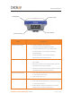
Configuring Through a Web Browser 5. Once you log in, the web page appears as follows: This web page shows the configuration menus on the left of the browser window, and the setting on the right. Each configuration menu contains the related Submenus to configure the receiver and monitor receiver performance. This chapter describes each configuration menu. To view the web page in another language, select the corresponding language name from the dropdown list on the upper right corner of the web page.
Configuring Through a Web Browser 5.1 Status Menu This menu provides a quick link to review the receiver's position information, satellites tracked, runtime, current data log status, current outputs, available memory, and more. 5.1.1 Position Submenu This page shows the relevant position information about the receiver's position solution which including the position, DOP values, satellites used and tracked, and the receiver clock information. 5.1.
Configuring Through a Web Browser 5.1.3 Google Map Submenu Tap this submenu to show the location of the receiver on Google map. 5.2 Satellites Menu Use the Satellites menu to view satellite tracking details and enable/disable GPS, GLONASS, BDS and Galileo constellations. These menus include tabular and graphical displays to provide all required information on satellite tracking status.
Configuring Through a Web Browser 5.2.1 Tracking Table Submenu Provides the status of satellites tracked in general, such as the satellite ID, satellite type, attitude angle, azimuth angle, L1 SNR, L2 SNR, L5 SNR and enable/disable status of each one. 5.2.2 Tracking Info. Table Submenu The following figure is an example of satellite track diagram page. Users can determine the satellite types and the corresponding SNR of L-band carriers to be displayed in any combination.
Configuring Through a Web Browser 5.2.3 Tracking Skyplot Submenu The following figure is an example of Skyplot page.
Configuring Through a Web Browser 5.2.4 Satellite Activation Submenu Use this menu to enable or disable satellites. 5.
Configuring Through a Web Browser 5.3.1 Description This submenu shows the receiver information and reference station information, including antenna related information, elevation mask angle, reference station work mode and position, etc. 5.3.2 Antenna Configuration Submenu Use this screen to configure all the items related to the GNSS antenna.
Configuring Through a Web Browser accuracy of logged data files and broadcast correction data significantly: For Reference Station Mode: There are three modes available: a) Auto Rover: The receiver will serve as a rover after this mode is enabled, and then receive correction data through the working mode set last time. 5.3.4 Receiver Reset Submenu Use this screen to completely or partially reset the receiver: 5.3.
Configuring Through a Web Browser 5.3.6 User Management Submenu 5.3.7 USB Function Switch Use this screen to set i73 work as APIS base. 1.
Configuring Through a Web Browser 2. Install the driver for i73 RNDIS a) Right click RNDIS, and select update driver, and choose Browse my computer for driver software.
Configuring Through a Web Browser b) Select Let me pick from a list of available drivers on my computer, and click next c) Then there will appear a hardware type list. In the list, select Network adapters. d) Then find Microsoft in the Manufacturer list, and select Remote NDIS based Internet Sharing Device in the model list.
Configuring Through a Web Browser 3. Config IP for i73. a) After installing the driver, there will show another Ethernet connection in Network connections. b) Go to properties, and double click IPV4 to change the IP address.
Configuring Through a Web Browser c) Change the IP address, Subnet mask and Default gateway as following: 4.Login into i73 webpage in Chrome by inputting: 192.168.253.1, keep same as the default gateway.
Configuring Through a Web Browser 5.Config i73 to connect Wifi and work as APIS base. a) Go to Module Setting -> WiFi, change WiFi mode to WiFi Terminal. b) Click Start to searching the wifi and connect. c) Go to Receiver Configuration -> Reference Station Settings. Set i73 as auto base, and get the base station.
Configuring Through a Web Browser d) Go to I/O settings, in RTK Client, config it. e) Connect Connect and config it as APIS base, use local APIS address. Then click Confirm to set. f) After send correction data to APIS server successfully, the RTK Client option will become green background.
Configuring Through a Web Browser g) Then set rover as APIS rover, and it will get fix solution. 5.3.8 HCPPP Settings Reserved for HCPPP. 5.4 Data Recording Menu Use the Data Logging menu to set up the receiver to log static GNSS data and to view the logging settings. You can configure settings such as observable rate, recording rate, continuous logging limit, and whether to auto delete old files when memory is low. This menu also provides the controls for the FTP push feature: 5.4.
Configuring Through a Web Browser To edit the settings of each session, click the Modify button to the right of the required session, and then the Recording Edit screen appears: Click advanced to see more settings.
Configuring Through a Web Browser In this screen, you can configure all the data logging parameters, and determine whether the recording files will be affected by the FTP Push. The parameters are mainly as follows: ¾ Auto Record: on or off. ¾ Sample Interval: Select the observable rate from the dropdown list. ¾ Elevation Mask: Enter the elevation mask. ¾ Duration Time: Set the duration of data logging. ¾ Site Name: Enter the name of the site. ¾ Antenna Height: the measured height value.
Configuring Through a Web Browser Tap button to save the settings and back to the Log Settings screen. Also, users can click to abandon the changed settings and back to Log Settings screen. Note – To modify data logging parameters, make sure the data logging session is switched off. To switch on or off ANY data logging session, tap the ON or OFF button on the right of the required session.
Configuring Through a Web Browser 5.4.3 FTP Push Log Submenu Shows the related information about the recorded filed that be pushed. And users can tap Clear Ftp Send Log button in the upper right corner to clear the log of FTP Push operations. 5.4.4 Data Download Submenu In this submenu, users can download the data files that recorded in the internal storage through the internal FTP site. 1.
Configuring Through a Web Browser The default logon account for the internal FTP site is: ¾ User name: ftp ¾ Password: ftp 2. Click the directory named as “repo” to view and download the files currently stored on the receiver: 3. To find the file need to be downloaded, click the name of data logging session → the date of file that be recorded → the format of the file → the name of the target file. 4. To download a file, left-click the name of the target file → download the file according to the prompts.
Configuring Through a Web Browser 5.5 IO Settings Menu Use the IO Settings menu to set up all receiver outputs and inputs. The receiver can output CMR, RTCM, Raw data, Ephemeris data, GPGGA, GPGSV, on TCP/IP, UDP, serial port, or Bluetooth ports. 5.5.1 IO Settings Submenu The following figure shows an example of the screen that appears when you select this submenu. (serial port setting is reserved menu) In this submenu, users can configure 6 types of input and output settings. 1.
Configuring Through a Web Browser ¾ Connection Protocol: APIS_BASE ¾ Connection Protocol: APIS_ROVER CHCNAV i73 GNSS USER GUIDE | 2020-8 P a g e | 54
Configuring Through a Web Browser ¾ Connection Protocol: TCP 2. TCP/UDP_Client/NTRIP Server Tap the Connect button on the right of required TCP/UDP Client → the IO Settings screen will appear → select the connection protocol from TCP, UDP,NTRIP1.0 and NTRIP2.0 → enter the IP and Port of the target server → configure messages that you want to output to the target server → click to save and complete the connection.
Configuring Through a Web Browser ¾ Connection Protocol: UDP ¾ Connection Protocol: NTRIP1.
Configuring Through a Web Browser ¾ Connection Protocol: NTRIP2.
Configuring Through a Web Browser 3. TCP Server/NTRIP Caster Tap the Connect button to the right of required TCP Server/NTRIP Caster→ the IO Settings screen will appear → select one of the connection protocols between NTRIP and TCP → configure the other related parameters → click server.
Configuring Through a Web Browser ¾ Connection Protocol: NTRIP 4. Bluetooth Tap the Settings button to the right of Bluetooth → the Bluetooth Set screen will appear → configure the messages that you want to transmit through Bluetooth → click save the settings and start to transmit.
Configuring Through a Web Browser 5.6 Module Setting Menu Use this menu to check module information, configure WiFi, bluetooth, radio related settings. 5.6.1 Description Submenu Use this submenu to check the information of WiFi module, bluetooth module and radio module. 5.6.2 WiFi Submenu Use this submenu to turn on/off WiFi function and modify password.
Configuring Through a Web Browser 5.6.3 Bluetooth Settings Submenu Use this submenu to turn on/off bluetooth function and modify PIN number. 5.6.4 Radio Settings Submenu Use this submenu to turn on/off radio function and configure radio parameters.
Configuring Through a Web Browser 5.
Configuring Through a Web Browser 5.7.1 Firmware Info Submenu Use this submenu to check the current firmware information. The following figure shows an example of the firmware information. 5.7.2 Hardware Version Submenu Use this submenu to check the hardware information, including main board version and core board version: 5.7.3 Config File Submenu Use this submenu to update Configuration File.
Configuring Through a Web Browser 5.7.4 System Log Download Submenu Use this submenu to download the system log of the receiver. 5.7.5 User Log Submenu Use this submenu to download the user log. Tap Download to download current user log; Tick items that you want to see on the user log and tap confirm button to confirm selected user log. 5.7.6 Firmware Update Submenu Use this submenu to load new firmware to the receiver across the network.
Configuring Through a Web Browser Notes x It may take about 3 or 4 minutes to complete the firmware upgrading. Do not touch the power button or unplug the power until the upgrading process finishes, or damage will be caused to the receiver. x The receiver will restart after the firmware upgrading is done, so users need to reconnect the receiver with your computer via Wi-Fi, and then log-in the receiver through a web browser to continue the configuration. 5.7.
Configuring Through a Web Browser CHCNAV i73 GNSS USER GUIDE | 2020-8 P a g e | 66
FCC STATEMENT This device complies with Part 15 of the FCC rules. Operation is subject to the following two conditions: 1) this device may not cause harmful interference, and 2) this device must accept any interference received, including interference that may cause undesired operation. Note: This equipment has been tested and found to comply with the limits for a Class B digital device, pursuant to part 15 of the FCC Rules.