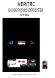
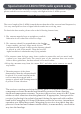
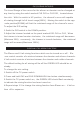
MERITRC 6CH 2.4GHZ FHSS RADIO CONTROLSYSTEM MT-602 CH6 CH5 CH2 D/R CH1 D R D/R CH2 CH1 SHANGHAI MERIT TECHNOLOGY CORP.
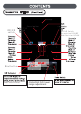
CH2 D/R switch CH1 D/R Switch Up position D/R-OFF Down Position D/R-ON CH2 D R CH6 CH5 D/R Bind button and Function Mode. CH2 CH1 CH1&CH2 D/R travel range adjustment.
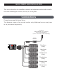
ADJUSTMENT AND INSTALLATION This section describes the installation method and adjustment method after installation when installing the receiver, servos, etc. to the plane. Connections Connection example is shown below. The diagram shown is for aircraft models only.Additional servos may have to be purchased separately. To Battery NOTE:NEVER use dry battery as it cause malfunction.
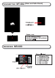
TRANSMITTER MT-602 (Rear and Side Panel) " RECEIVER MR-600 "
Special note for 2.4GHz FHSS radio system setup Since the 2.4GHz have different characteristics than that of the conventional frequencies, please read this section carefully to enjoy safe flight with the 2.4GHz system. Receiver ’s Antenna installation The wave length of the 2.4GHz is much shorter than that of the conventional frequencies, it is very susceptible to loss of signal which results in a receiving error. To obtain the best results, please refer to the following instructions; 1.
Transmitter antenna 1. The transmitter antenna is adjustable so please make sure that the antenna is never pointed directly at the model when flying as this creates a weak signal for the receiver. 2. Keep the antenna perpendicular to the transmitter's face to create a better RF condition for the receiver. Of course this depends on how you hold the transmitter, but in most cases, adjusting the transmitter antenna so that it is perpendicular to the face will give the best results.
Binding Setup(Pair Procedure) Programming a receiver to recognize the code of only one specific transmitter. If you change transmitters or add a receiver, you must re-bind before operating your model. 1. Place the transmitter and the receiver close to each other (within one meter). Turn the power switch on the transmitter to the ON position. 2. Press and hold the receiver setup button,then turn the power switch to the ON position. The receiver LED will flash quickly.
2.Walk away from the model while simultaneously operating the controls.Have an assistant stand by the model and signal what the controls are doing to confirm that they operate correctly.You should be able to walk approximately 30 - 50 paces from the model without losing control. 3.If everything operates correctly,return to the model.Set the transmitter in a safe,yet accessible location so it will be within reach after starting the engine.
CH1,CH2 DUAL RATE (D/R) The travel Range of the servos for the aileron or elevator can be changed at any time by using the switch marked CH1 D/R or CH2 D/R,located above the stick。With the switch in UP position,the channel’s servo will capable of rotating through its full travel range(100%)。Moving the switch to the opp-osite position(DOWN) will limit the rotational range of the channel’s servo。 To adjust the D/R setting: 1.Swith the D/R switch to the DOWN position。 2.
MODE 1、MODE 2 STICK SETTING This function changes the stick mode of transmitter。 Note:This will not change the throttle Ratchet etc。Those are mechanical changes that must be performed by specific technician。 To change the MODE setting: 1.Switch off the TX power switch。 2.Press and hold CH1 and CH4 LEFT&RIGHT trim button simultaneously。 3.
Transmitter Operation and Movement of Each Servo Before making any adjustments, learn the operation of the transmitter and the movement of each servo. (In the following descriptions, the transmitter is assumed to be in the standby state.) AILERON OPERATION When the aileron stick is moved to the right, the right aileron is raised and the left aileron is lowered, relative to the direction of flight, and the plane turns to the right.
WARNING Connector Connection Insert the receiver, servo, and battery connectors fully and firmly. If vibration, etc. causes a connector to work loose during flight, the plane may crash. Receiver Vi brationpr oofing / Waterpr oofing Vibrationproof the receiver by wrapping it in sponge rubber or some such material. If the receiver may get wet, waterproof it by placing it in a plastic bag. If the receiver is subjected to strong vibration and shock, or gets wet, it may operate erroneously and cause a crash.
FCC RF Exposure Information and Statement This device complies with part 15 of the FCC rules. Operation is subject to the following two conditions: (1) this device may not cause harmful interference, and (2) this device must accept any interference received, including interference that may cause undesired operation. NOTE: The manufacturer is not responsible for any radio or TV interference caused by unauthorized modifications to this equipment.