
User's Manual

L710HG EVB User Manual
Copyright© Shanghai Mobiletek Communication Ltd 15
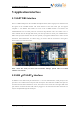
Figure5-6: Chinese standard earphone
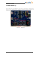
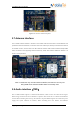
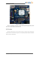
5.7 Antenna interface
The L710HG antenna interface is located on the module load board mounted on the EVB board and
provides two antenna interfaces, one of which is the main antenna port, directly connected to the antenna
for wireless function, and the other is the GPS antenna interface. Main antenna interface adopts SMA
head, connected to the supporting external antenna by cable; GPS antenna USES IPX interface. As
shown in the figure below:
Figure5-7: Function module load plate and antenna interface
Note: L710HG has only one main antenna interface, and the user can only use
ANT_MAIN as the antenna interface when it is actually used.
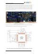
5.8 Audio interface(TBD)
The L710HG module supports 1-channel PCM channel, which can also be reused as I2S signal.
When using, switch S2 and S3 are needed to cooperate. The switch S2 is a software and hardware
switch. When switching S2 to the top, the software can pull GPIO25 high level to make the power
supply and crystal vibration of CODEC; When switching S2 to the bottom, the hardware