
Data Sheet
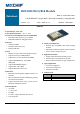
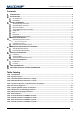
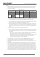
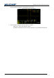
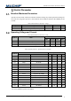
Table Of Contents

EMC3080 Series Wireless Module Data Manual
Copyright of Shanghai MXCHIP Information Technology Co., Ltd.
7
Notes:
1. Module working mode selection signal. During the startup phase, the module detects the level of
these pins and enters a specific working state. The correspondence between level and working
mode is shown in Table 3:
Table 2 operation mode
Operation mode
PA_0
Default: 0
PA_13
Default: 0
PA_20(BOOT)
Default: 1
PA_19(EASYLINK)
Default: 1
ISP Program Mode
1
1
not detect
not detect
Test mode
1
0
not detect
not detect
Normal
QC
0
not detect
0
0
ATE
0
1
APP
1
not detect
(1). ISP Program Mode, Test mode and Normal mode are detected by hardware at startup. PA_0
and PA_13, because it is a function of hardware solidification, it cannot be modified.
(2). QC, ATE and APP modes are judged by the firmware provided by MXCHIP, and the detection
conditions and functions can be adjusted by modifying the firmware.
(3). ISP Program Mode function contempt: In the startup phase, if the processor hardware detects
that the levels of PA_0 and PA_13 are high, it enters ISP programming mode. In the ISP
programming mode, the flash of the module can be programmed through UART2 (PA_16,
PA_15).
(4). Test mode is the reserved mode of the chip and will not be used.
(5). After the startup is completed, when the processor runs the firmware provided by MXCHIP, the
firmware detects the status of PA_20 and PA_19 to enter the corresponding working mode.
among them:
⚫ QC mode is used to self-check the hardware during production, and generate QC
information for the production device to check the quality of the module.
⚫ In the ATE mode, a series of serial commands are provided to make the radio frequency
in a specific transceiver mode, so that the instrument can be tested and calibrated.
⚫ APP is the normal working mode for running applications.
2. The UART2 serial port is used for the input / output of debugging information. Do not use it
during design, and provide as easy a way as possible to facilitate software development.
3. The CHIP_EN pin is an enable reset pin, which is active low and can be left floating if not used. Or
pull up 3.3V.
4. Please keep the unused pins floating. It should be noted that the IO port is in a floating state at
startup. If you need to configure the state of the pin through software, you need to wait until the
code in the bootloader starts to execute. The time from when the module is powered on to when
the code in the bootloader is executed will be affected by the flash startup time. Therefore, if you
need IO to be in a certain level state at startup, you need to use a 100k resistor on the pin to pull
up and down. Figure 3 shows the level change of the IO port whose software is configured as a low
level after being pulled up by an external 100K resistor in the floating state. It can be seen that the
time from the power-on of the module to the controllable IO port software is 69.4ms, and the time