
Data Sheet
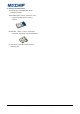
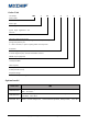
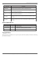
Table Of Contents
- Abstract
- 1. Introduction
- 2. Characteristic
- 3. Pin Definition
- 4. System memory space
- 5. ATE(RF Test Mode)
- 5.1. ATE Command
- 5.1.1. Start MP mode
- 5.1.2. Stop MP mode
- 5.1.3. Set Tx rate
- 5.1.4. Set operational channel
- 5.1.5. Set operational bandwidth
- 5.1.6. Set Tx power
- 5.1.7. Set antenna for Tx
- 5.1.8. Set antenna for Rx
- 5.1.9. Start air Rx mode
- 5.1.10. Start continuous Tx mode
- 5.1.11. Query air Rx statistics
- 5.1.12. Reset air Tx/Rx statistics
- 5.2. Example Command
- 5.1. ATE Command
- 6. Flash Programing
- 7. Electrical parameters
- 8. Antenna Information
- 9. Assembly size and PCB package
- 10. Production Guidelines
- 11. FCC and IC Information
- 11.1. FCC Warning
- 11.2. IC warning
- 11.3. Trace antenna designs
- 11.4. RF exposure considerations
- 11.5. Antennas
- 11.6. Label and compliance information
- 11.7. Information on test modes and additional testing requirements5
- 11.8. Additional testing, Part 15 Subpart B disclaimer
- 11.9. The module is limited to OEM installation ONLY.
- 11.10. The OEM integrator is responsible for ensuring that the end-user has no manual instructions to remove or install module.
- 11.11. The module is limited to installation in mobile or fixed applications
- 12. Package and Label
- Appendix 1: Sales and Technical Support Information

EMC328x Series Wireless Module Data Manual
Copyright of Shanghai MXCHIP Information Technology Co., Ltd.
2
Typical Application Power Consumption ................................................................................................................................... 24
Temperature ................................................................................................................................................................................... 24
RF Parameters ................................................................................................................................................................................ 24
7.6.1. EMC3280 ...................................................................................................................................................................................................................... 25
7.6.2. EMC3285 ...................................................................................................................................................................................................................... 25
Antenna Information .............................................................................................................................................. 26
PCB Antenna Parameters and Use .............................................................................................................................................. 26
8.1.1. EMC328x On-board PCB Antenna Parameter ................................................................................................................................................. 26
8.1.2. PCB Antenna use points ......................................................................................................................................................................................... 26
External antenna parameters and use ........................................................................................................................................ 27
Assembly size and PCB package........................................................................................................................... 28
Final assembly size chart .............................................................................................................................................................. 28
Recommended package drawing ................................................................................................................................................ 29
Production Guidelines ............................................................................................................................................ 31
Precautions .................................................................................................................................................................................... 32
Secondary Reflow Profile ............................................................................................................................................................. 32
Storage Condition ......................................................................................................................................................................... 34
FCC and IC Information .......................................................................................................................................... 35
FCC Warning .................................................................................................................................................................................. 35
IC warning ...................................................................................................................................................................................... 35
Trace antenna designs .................................................................................................................................................................. 36
RF exposure considerations ......................................................................................................................................................... 36
Antennas ........................................................................................................................................................................................ 37
Label and compliance information ............................................................................................................................................. 37
Information on test modes and additional testing requirements5 ........................................................................................ 37
Additional testing, Part 15 Subpart B disclaimer ...................................................................................................................... 37
The module is limited to OEM installation ONLY. ..................................................................................................................... 38
The OEM integrator is responsible for ensuring that the end-user has no manual instructions to remove or install
module. ........................................................................................................................................................................................................ 38
The module is limited to installation in mobile or fixed applications .................................................................................... 38
Package and Label .................................................................................................................................................. 39
Package Information .................................................................................................................................................................... 39
Product Label ................................................................................................................................................................................. 39
Appendix 1: Sales and Technical Support Information ............................................................................................. 40
Table Catalog
Table 1 Pin Definition ........................................................................................................................................................ 9
Table 2 Low Power Pin Definition ................................................................................................................................. 10
Table 3 Special function capture pin ............................................................................................................................ 10
Table 4 Firmware special function capture pin........................................................................................................... 11
Table 5 System Storage Space ....................................................................................................................................... 13
Table 6 Flash Storage space partition .......................................................................................................................... 14
Table 7 Flash Programed Method ................................................................................................................................. 19
Table 8 Absolute Maximum Parameter: Voltage ....................................................................................................... 23
Table 9 Operating parameters: voltage and current ................................................................................................. 23
Table 10 Operating Parameters:Digital IO DC Characteristics(3.3V) ............................................................... 23
Table 11 Operating Parameters: Digital IO DC Characteristics(1.8V) ................................................................. 24
Table 12 Typical Application Power Consumption .................................................................................................... 24
Table 13 Storage Temperature and Operating Temperature ................................................................................... 24