
Data Sheet
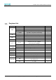
Table Of Contents
- Abstract
- 1. Introduction
- 2. Characteristic
- 3. Pin Definition
- 4. System memory space
- 5. ATE(RF Test Mode)
- 5.1. ATE Command
- 5.1.1. Start MP mode
- 5.1.2. Stop MP mode
- 5.1.3. Set Tx rate
- 5.1.4. Set operational channel
- 5.1.5. Set operational bandwidth
- 5.1.6. Set Tx power
- 5.1.7. Set antenna for Tx
- 5.1.8. Set antenna for Rx
- 5.1.9. Start air Rx mode
- 5.1.10. Start continuous Tx mode
- 5.1.11. Query air Rx statistics
- 5.1.12. Reset air Tx/Rx statistics
- 5.2. Example Command
- 5.1. ATE Command
- 6. Flash Programing
- 7. Electrical parameters
- 8. Antenna Information
- 9. Assembly size and PCB package
- 10. Production Guidelines
- 11. FCC and IC Information
- 11.1. FCC Warning
- 11.2. IC warning
- 11.3. Trace antenna designs
- 11.4. RF exposure considerations
- 11.5. Antennas
- 11.6. Label and compliance information
- 11.7. Information on test modes and additional testing requirements5
- 11.8. Additional testing, Part 15 Subpart B disclaimer
- 11.9. The module is limited to OEM installation ONLY.
- 11.10. The OEM integrator is responsible for ensuring that the end-user has no manual instructions to remove or install module.
- 11.11. The module is limited to installation in mobile or fixed applications
- 12. Package and Label
- Appendix 1: Sales and Technical Support Information

EMC328x Series Wireless Module Data Manual
Copyright of Shanghai MXCHIP Information Technology Co., Ltd.
2
Peripheral List
Item
Peripherals
Comment
Note
UART
HS_UART1
Internal connection to Bluetooth
1
HS_USI_UART
1
LP_UART1
Low power mode wake up
1
LP_UART0
Log UART,Low power mode wake up
1
SPI
HS_SPI1
Supports main mode, clock up to 25MHz
1
HS_USI_SPI
Support master / slave mode, clock up to 25MHz
1
RTC
RTC_OUT
1
EXT_32K
1
IR
IR
1
I
2
C
LP_I2C
Standard mode (up to 100Kbps)
Fast mode (up to 400Kbps)
1
HS_USI_I2C
Standard / fast / high speed mode (up to 3.33Mbps)
1
HS_PWM
LP_PWM
HS_PWM0 ~ 17
8
LP_PWM0 ~ 5
Support low power mode
4
DMIC
DMIC
1
SGPIO
SGPIO
1
Key-Scan
Key-Scan
4x2/3x3
Wake Pin
Wake Pin
Wake up from deep sleep mode
6
HS_TIM4_TRIG
HS_TIM5_TRIG
HS_TIM4_TRIG
Timer capture pin
1
HS_TIM5_TRIG
Timer capture pin
1
Analog Pin
USB
USB master-slave mode, the main mode supports
mass storage class
1
ADC
0 ~ 3.3V
3