
Data Sheet
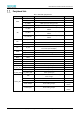
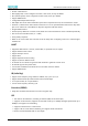


Table Of Contents
- Abstract
- 1. Introduction
- 2. Characteristics
- 3. Pin Definition
- 4. System memory Space
- 5. ATE(RF Test Mode)
- 5.1. Wi-Fi ATE Command
- 5.1.1. Start MP mode
- 5.1.2. Stop MP mode
- 5.1.3. Set Tx rate
- 5.1.4. Set operational channel
- 5.1.5. Set operational bandwidth
- 5.1.6. Set Tx power
- 5.1.7. Set antenna for Tx
- 5.1.8. Set antenna for Rx
- 5.1.9. Start air Rx mode
- 5.1.10. Start continuous Tx mode
- 5.1.11. Query air Rx statistics
- 5.1.12. Reset air Tx/Rx statistics
- 5.2. Bluetooth ATE Command(TBD)
- 5.3. Example Command
- 5.1. Wi-Fi ATE Command
- 6. Flash Programming
- 7. Electrical Parameters
- 8. RF Parameter
- 9. Antenna Information
- 10. Dimensions and Production Guidance
- 11. Production Guidelines
- 12. FCC and IC Information
- 12.1. FCC Warning
- 12.2. IC warning
- 12.3. Trace antenna designs
- 12.4. RF exposure considerations
- 12.5. Antennas
- 12.6. Label and compliance information
- 12.7. Information on test modes and additional testing requirements5
- 12.8. Additional testing, Part 15 Subpart B disclaimer
- 12.9. The module is limited to OEM installation ONLY.
- 12.10. The OEM integrator is responsible for ensuring that the end-user has no manual instructions to remove or install module.
- 12.11. The module is limited to installation in mobile or fixed applications
- 13. Packaging and Label Information
- 14. Sales and Technical Support Information

EMC3380 Series Wireless Module Data Manual
Copyright of Shanghai MXCHIP Information Technology Co., Ltd.
10
▪ Provide 2 SPI interfaces
▪ SPI0 (High speed): can be configured as master / slave mode, clock up to 50MHz.
▪ SPI1 (Normal speed): can be configured as master mode, clock up to 25MHz
▪ Support DMA transfer
▪ Configurable independent interrupt
▪ FIFO depth: The receive and transmit FIFO queues have a depth of 64 words, and each word has 16 bits.
▪ Hardware / software slave device selection function: You can use special hardware slave device chip select
pins or use software to control GPIOs as chip select signals for SPI slave devices.
▪ Programmable features:
▪ Clock frequency: When set to master mode, the bit rate of data transmission can be controlled dynamically
▪ The size of each transmitted data (4 ~ 16 bits)
▪ Clock polarity and phase
▪ When set to receive serial data in master mode, the delay time of sampling can be set to achieve higher
serial bit rate
UART
▪ Supported UART format: 1 start bit, 7/8 data bits, 0/1 parity bit and 1/2 stop bit
▪ Support hardware flow control
▪ Support interrupt control
▪ Support IrDA
▪ Support loopback mode for testing
▪ Support TX, RX use different clocks
▪ Tx channel can use a baud rate generator with decimals to generate accurate clock
▪ Rx channel supports low power mode
▪ Can monitor and eliminate the baud rate error and drift on the Rx channel
▪ Support DMA transfer
IR (Infra Ray)
▪ Support carrier frequency range: 25KHz to 500KHz, duty cycle: 1/2 to 1/5
▪ Support infrared diode input and infrared receiver module input
▪ 32 * 4 bytes Tx FIFO, 32 * 4 bytes Rx FIFO
▪ Can set carrier frequency and duty cycle
One wire (SGPIO)
▪ Single-line communication interface for secure encryption chip
I2C
▪ Two-wire I2C serial interface, consisting of data line (SDA) and clock line (SCL)
▪ Supports one I2C interface, supports two standard modes up to 100Kbps and high-speed modes up to
400Kbps, and supports clock stretching
▪ Support I2C master device or slave device
▪ Support 7-bit or 10-bit address addressing, and support mixed transmission
▪ Receive and transmit buffer with 16 word depth