
Data Sheet


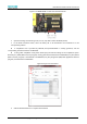


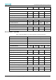
Table Of Contents
- Abstract
- 1. Introduction
- 2. Characteristics
- 3. Pin Definition
- 4. System memory Space
- 5. ATE(RF Test Mode)
- 5.1. Wi-Fi ATE Command
- 5.1.1. Start MP mode
- 5.1.2. Stop MP mode
- 5.1.3. Set Tx rate
- 5.1.4. Set operational channel
- 5.1.5. Set operational bandwidth
- 5.1.6. Set Tx power
- 5.1.7. Set antenna for Tx
- 5.1.8. Set antenna for Rx
- 5.1.9. Start air Rx mode
- 5.1.10. Start continuous Tx mode
- 5.1.11. Query air Rx statistics
- 5.1.12. Reset air Tx/Rx statistics
- 5.2. Bluetooth ATE Command(TBD)
- 5.3. Example Command
- 5.1. Wi-Fi ATE Command
- 6. Flash Programming
- 7. Electrical Parameters
- 8. RF Parameter
- 9. Antenna Information
- 10. Dimensions and Production Guidance
- 11. Production Guidelines
- 12. FCC and IC Information
- 12.1. FCC Warning
- 12.2. IC warning
- 12.3. Trace antenna designs
- 12.4. RF exposure considerations
- 12.5. Antennas
- 12.6. Label and compliance information
- 12.7. Information on test modes and additional testing requirements5
- 12.8. Additional testing, Part 15 Subpart B disclaimer
- 12.9. The module is limited to OEM installation ONLY.
- 12.10. The OEM integrator is responsible for ensuring that the end-user has no manual instructions to remove or install module.
- 12.11. The module is limited to installation in mobile or fixed applications
- 13. Packaging and Label Information
- 14. Sales and Technical Support Information

EMC3380 Series Wireless Module Data Manual
Copyright of Shanghai MXCHIP Information Technology Co., Ltd.
28
Flash Programming
There are several ways to program the module's Flash to burn specific function firmware. The application
scenarios and restrictions of various burning methods are as follows:
Table 8 Flash programming methods
Method
Interface
COMM Pin
Burn
Mode
Preparation
PA7
Simulation debugger
SWD
PA27,PB3
-
development environment
and JTAG debugger
Serial Port download mode
UART0/UA
RT1
PA7,PA8
0
Image Tool Burning Software
BAT Burn System
SWD
PA27,PB3
-
BAT Burn System
Note: PA7 powers up high level by default.
The application scenarios of each burning method are as follows:
Simulation debugger: Burn during module development and debugging.
Serial port download mode: Batch programming of modules on the production line.
BAT programming system: The module is reprogrammed on the module or product production line and can
be used for the unique ID of the programming device.
In summary, it is recommended to lead PA7, PA8, PA27 and PB3 on the user's mainboard as the burning test
points for programming, which is convenient for development and production.
Burning with the emulator debugger
When using the MXOS system to develop module firmware, burn the generated firmware into the module
through the compile command in the development environment MiCoder. About MiCoder development
environment build, please refer to related documents. The hardware emulator usually selects JLink, and the
connection method is shown in Figure 5.
Figure 5 JLink Connection schematic diagram
Add the download parameter to the compile command to download the currently compiled
firmware. Because the development environment needs to be installed, it is not suitable for module batch
factory programming.
For example, to compile the Helloworld application, execute the command.