
User's Manual

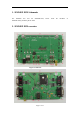
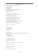
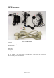
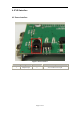


Table Of Contents

Figure 2: BOTTOM view
A: 80pin connector, SIM548Z module interface
B1-B5: LED indicator
B1: VBAT ON/OFF
B2: GSM net status
B3: The GSM part of the module ON/OFF status
B4: 1PPS output for GPS part
B5: GPS TX/RX status
C1-C9: Key control for various functions
C1: GSM part power-up / power down control (button Z1)
C2: VBAT ON/OFF control (shifter S2)
C3: VCHG ON/OFF control (shifter S5)
C4: GSM part program download control (shifter S1)
C5: GPS part power ON/OFF control (shifter S7)
C6: GPS part reset control (button Z2)
C7: GPS part RX/TX LED status selective shifter (shifter S6)
C8: GPS part wake up control (shifter S3)
C9: GPS part program download control (shifter S4)
D: Power source adapter interface
E1-E3: Audio interface
E1: Handset interface
E2: Headphone interface
E3: Buzzer
F1-F4: Serial ports
F1: Main serial port for downloading, AT command transmitting, data exchanging
F2: Debug serial port
F3: GPS part serial port A
F4: GPS part serial port B
G1-G2: Hole for antenna fixed
G1: Hole for GSM antenna fixed
G2: Hole for GPS antenna fixed
H: Expand port, such as keypad port, serial ports, display port
I1-I4: Hole for EVB board fixed
J: SMA connector for 1PPS output
K: SIM card connector
L: 3.3V Back-up battery for GPS part
Page 4 of 12