
User's Manual


SIM800 Document
- 5 -
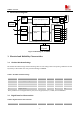
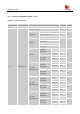
2. Detail Block Diagram
Analog base
band
Digital base
band
Power management unit
Radio
Frequency
Power
supply
Analog Interface
Digital Interface
UART
SIM
GPIOs
RTC
Audio
ADC
RF
BT
FM
USB
KEY
PCM、SPI、SD
26M
Crystal
32K
Crystal
Figure 3: Block diagram of SIM800
3. Electrical and Reliability Characteristics
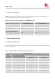
3.1. Absolute Maximum Ratings
The absolute maximum ratings stated in following table are stress ratings under non-operating conditions. Stresses
beyond any of these limits will cause permanent damage to SIM800.
Table 1: Absolute maximum ratings
Symbol
Parameter
Min
Typ
Max
Unit
VBAT
Power supply voltage
-
-
4.5
V
VBUS
-
-
30
V
VBUS
I
I
*
Input current
-
-
8
mA
I
O
*
Output current
-
-
8
mA
*
These parameters are for digital interface pins, such as keypad, GPIO, I
2
C, UART, LCD and DEBUG.
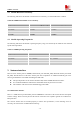
3.2. Digital Interface Characteristics
Table 2: Digital interface characteristics
Symbol
Parameter
Min
Typ
Max
Unit