
User's Manual


Smart Machine Smart Decision
- 12 -
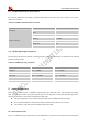
Figure 1: GPS active antenna matching circuit
There are some suggestions to components placing and lying for GSM and Bluetooth RF traces:
The RF connector is used for conducted test, so keep it as close as pin RF_ANT;
Antenna matching circuit should be closed to the antenna;
Keep the RF traces as 50Ω;
The RF traces should be kept far away from the high frequency signals and strong disturbing source.
5.3.1 GSM antenna
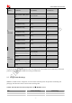
Model GSM antenna: WT-C&G-28-90
Frequency Range (MHz) 824 ~ 960 1710 ~ 1990
VSWR ≤1.5 (900MHz) ≤2 (1800MHz)
Gain (dBi): 3
Input Impedance (Ω): 50
Polarization Type: Vertical
Connector Type: SMA
Figure 7 GSM antenna
5.3.2 GPS antenna