
User's Manual


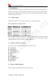

Table Of Contents
- Revision History
- Introduction
- Package Information
- Interface Application
- RF Specifications
- Electrical Specifications
- SMT Production Guide
- Packaging
- Appendix

Smart Machine Smart Decision
SIM7500A_User Manual_V1.022016-09-29
8
1 Introduction
This document describes the electronic specifications, RF specifications, interfaces, mechanical
characteristics and testing results of the SIMCom SIM7500 series. With the help of this document
and other software application notes/user guides, users can understand and use modules to design
and develop applications quickly.
1.1 Product Outline
The SIM7500A support many air-interface standards, refer to the following table.
Table 1: SIM7500 series frequency bands
Standard
Frequency
SIM7500A
WCDMA
BAND2
BAND5
LTE
LTE-FDD B2
LTE-FDD B4
LTE-FDD B12
With a smallphysical dimension of 24*27*2.75 mm and with the functionsintegrated, the Module
can meet almost any space requirement in users’ applications, such as smart phones, PDA’s,
industrial handhelds, machine-to-machine, vehicle applications, etc.
1.2 Hardware Interface Overview
The interfaces that are described in detail in the next chapters include:
● Power Supply
● USB Interface
● UART Interface
● USIM Interface
● GPIO
● ADC
● Power Output
● Current Sink Source
● PCM Interface
● I2C Interface
1.3 Hardware Block Diagram
The block diagram of the Module is shown in the figure below.