
User's Manual


Smart Machine Smart Decision
SIM7500A_User Manual_V1.00 2017-06-30
14
2.2 Pin Description
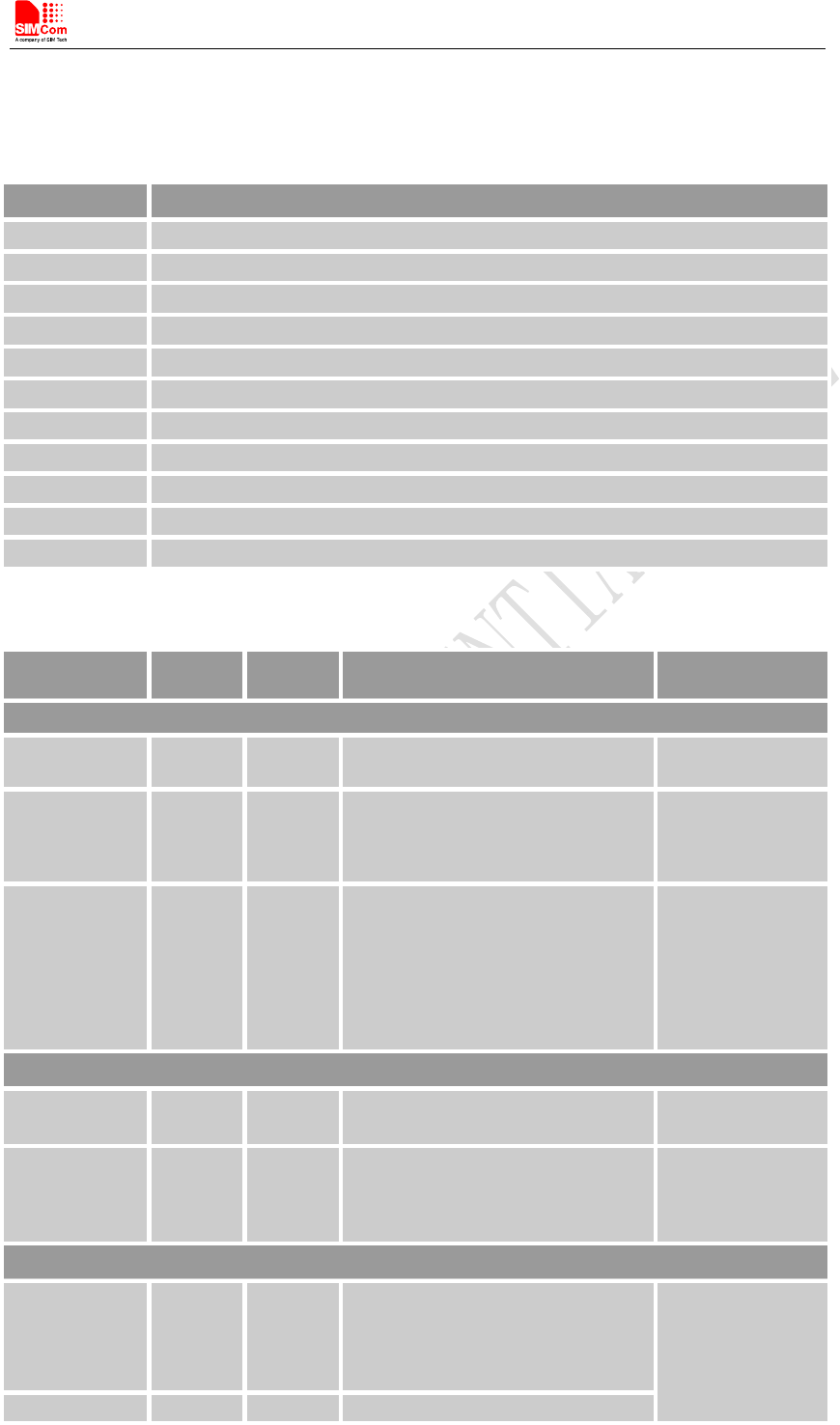
Table 4: IO parameters definition
Pin type Description
PI Power input
PO Power output
AI Analog input
AIO Analog input/output
I/O Bidirectional input /output
DI Digital input
DO Digital output
DOH Digital output with high level
DOL Digital output with low level
PU Pull up
PD Pull down
Table 5: Pin description
Pin name Pin No.
Default
status
Description Comment
Power Supply
VBAT
33,34 PI
Power supply, voltage range: 3.4~
4.2V.
L11_1V8 23 PO
1.8V output with Max. 50Ma
current output for external circuit,
such as level shift circuit.
If unused, keep it
open.
GND
1, 3, 6,
15,16,22
,28,29,3
1,32,35,
43,44,46
,47,53,5
4,56
Ground
System Control
PWRKEY 30 DI,PU
System power on/off control input,
active low.
Default 0.8V
RESET 24 DI, PU
System reset control input, active
low.
RESET has been
pulled up to 1.8V
via a resistor
internally.
USIM interface
USIM_DATA 10 I/O,PU
USIM Card data I/O, which has
been pulled up via a 100KR resistor
to USIM_VDD internally.
All lines of USIM
interface should
be protected
against ESD.
USIM_RST 13 DO USIM Reset