
Data Sheet
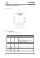
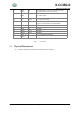
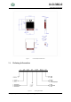
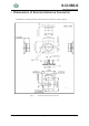
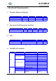
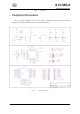
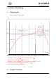
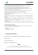
Table Of Contents
- 1 Module Overview
- 1.1 Features
- 1.2 Description
- 1.3 Applications
- CONTENTS
- LIST OF FIGURES
- LIST OF TABLES
- HISTORY
- 2 Hardware Introduction
- 2.1 Pin Layout
- 2.2 Pin Description
- 2.3 Physical Dimensions
- 2.4 Ordering Information
- 3 Dimensions of External Antenna Connector
- 4 Electrical Characteristics
- 4.1 Absolute Maximum Ratings
- 4.2 Recommended Operating Conditions
- 4.3 ESD
- 4.4 WiFi/BLE RF Standards
- 5 Peripheral Schematics
- 6 Product Handling
- 6.1 Reflow Profile
- 6.2 Storage Conditions
- 6.3 Device Handling Instruction (Module IC SMT Prepara
- 7 Contact Information

X-C13SG-0
802.11bgn and BLE SoC
Shanghai ChipFresh Internet of Things Technology Co., Ltd
14
6 Product Handling
6.1
Reflow Profile
Solder the module in a single reflow.
0 50
100 150 200 250
Ramp-up zone — Temp.: 25 ~ 150
℃
Time: 60 ~ 90 s Ramp-up rate: 1 ~ 3 ℃/s
Preheating zone — Temp.: 150 ~ 200
℃
Time: 60 ~ 120 s
Reflow zone — Temp.: >217
℃
7LPH:
60 ~ 90 s; Peak Temp.: 235 ~ 250
℃
Time: 30 ~ 70 s
Cooling zone — Peak Temp. ~ 180
℃
Ramp-down rate: –1 ~ –5
℃
/s
Solder — Sn-Ag-Cu (SAC305) lead-free solder alloy
Time (sec.)
50
25
0
100
Ramp-up zone
1 ~ 3 ℃/s
Soldering time
> 30 s
Cooling zone
–1 ~ –5
℃
/s
Reflow zone
>217 ℃ 60
~
90s
Preheating zone
150 ~ 200
℃
60 ~ 120 s
250
217
200
Peak Temp.
235 ~ 250
℃
Figure 7. Reflow Profile
6.2 Storage Conditions
℃