OWNER'S MANUAL Bull Shark 40xs Bull Shark 50 Tiger Shark 80
This manual must be considered as an integral part of your outboard motor and has to be kept with it, also if the motor is resold. Selva joint-stock CO. reserve the right to change its product at any moment, except for the essential specifications, which will be kept as they are. Any reference to products or details of a third party has only an informative purpose and it doesn't represent an obligation. Selva joint-stock CO.
INTRODUCTION ATTENTION Before operating this outboard motor, read this Owner's Manual carefully and completely, pay attention especially to the safety measures and rules. Your safety and other people's safety do not depend only on your ability at using the motor, but they depend also on your knowledge and on the efficiency of the motor as well as on the respect of the laws and regulations relating to the use of outboard motors.
OUTBOARD MOTOR IDENTIFICATION DATA SERIAL NUMBER RECORD This data is stamped on the label attached on the clamp bracket, as shown on the picture 1. When you receive your new SELVA outboard motor write down the serial number, it will be useful to you in case you will have to order spare parts or for reference if your outboard motor should be stolen. Write down the identification number and the model of your outboard motor in the spaces below.
CONTENTS GENERAL INFORMATION............................................................. 1 Introduction .................................................................................... 2 Outboard identification data .......................................................... 3 Serial number record ..................................................................... 3 Directions for use. Basic safety measures................................ 5 Specifications ..............................................
DIRECTIONS FOR USE BASIC SAFETY MEASURES To use the outboard motor you must have all the requisites provided by law (physical suitability, insurance, government duties, registration, and so on). We suggest you become familiar with your boat equipped with SELVA motor in places, which are not too crowded. Use fuels and oils suitable for the engine, which are listed in the "greasing chart ". Check every so often the oil level and the fuel level.
Any alteration attempted on your motor or the removal of any of its basic elements, can compromise its safety, it is against the law, and it means the immediate loss of your guarantee. The engine operator must attach the engine stop switch lanyard to his wrist when the motor is on. Picture No. 5. Observe the laws in force. Never sit on the motor. Picture No. 6. Pay great attention to the weather conditions. Listen to the weather forecast and take the warnings to the sailors into consideration.
SPECIFICATIONS MODEL Bull Shark 40xs - I684A POWER FULL THROTTLE RANGE PISTON DISPLACEMENT BORE X STROKE NUMBER OF CYLINDERS ENGINE TYPE FUEL ADMISSION AVERAGE CONSUMPTION FUEL FUEL TANK MOTOR OIL MOTOR OIL TANK CAPACITY CAMSHAFT OIL CAMSHAFT OIL TANK CAPACITY IGNITION SPARK LEAD ELECTRIC STARTING SPARK PLUGS EXHAUST COOLING PROPELLER GEAR SHIFT LEVER REC.GEARBOX OIL GEARBOX OIL QUANTITY TRIM ANGLE ADJUSTING SUSPENSIONS RECOMMENDED HEIGHT OF THE TRANSOMS WEIGHT (basic models Kg.) 40HP (29.
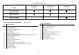
Swivel Bracket model chart MODEL BULL SHARK 40 XS BULL SHARK 50 TIGER SHARK 80 SWIVEL BRACKET SHOCK ABSORBER SWIVEL BRACKET POWER TRIM GWO37 SWIVEL BRACKET POWER TRIM GWO27 LOCATION OF MAIN COMPONENTS N° 1 2 3 4 5 6 7 8 9 10 11 12 13 14 15 16 17 Picture No.
Neutral gear accelerator control lever It allows to control the accelerator when the clutch is in the neutral position, to increase the number of r.p.m. you must pull it up.
WIRING DIAGRAMS Wires' colour CONTROL FUNCTIONS Motor G GL GB L O LBl R P Gy RBl BLb PR W WB WG WY Y YG YL YB YR Hood Hook. Device to fix the hood. To release it you have to turn the two handles counter clockwise. Picture No. 14 Fuel connector Inserting the connector you connect the fuel hose. Picture No. 15 Trim switches. (only models with Trim Tilt) It allows the insertion of the Trim Tilt device directly from the motor. Picture No.
12. Emergency cut-off switch SYMBOLS 13. Engine temperature Sensor (ETS) 14. Air temperature Sensor (ATS) 15. Throttle position sensor (TPS) 16. PC Connexion 17. Crankshaft sensor 18. Fuel injector cylinder #1 19. Fuel injector cylinder #2 20. Fuel injector cylinder #3 21. Electrical fuel pump 22. Main relay 23. Fuel pump relay 24. Temperature alarm relay 25. Power trim and tilt UP relay 26. Power trim and tilt DOWN relay 27. Fuse 10 A 28. Fuse 20 A 29. Fuse 15 A 30. ECU 31. Neutral switch 32.
THE USE OF THE OUTBOARD MOTOR PRELIMINARY CONTROLS CHART DETAIL Complete supply Right installation CHECK DESCRIPTION PAGE Check that the motor supply includes all the components that are in the detailed list. 13 Check the proper installation of your motor (the centre of the transom). 13 Check the proper mounting height of your motor. 13 Check the tightness of the clamp screws and of the hand levers. Check the proper installation of the remote control box.
Outboard motor mounting. Check the supply.
MOTOR FIXING TRIM ANGLE ADJUSTING Model with Swivel Bracket The trim angle is the inclination angle, that should be given to the motor in order to obtain an optimal performance from your boat. After having put the motor in the correct position, clamp the screws of the levers. Then make two holes in the transom in correspondence of the holes in the fixing brackets. Apply some dope on the holes made and on the screws to be used to fix the motor (which are with the motor).
Trim-angle adjusting - models with Shock Absorber Position of the remote control box Release the Shock Absorber through the control lever. Tilt the motor and keep it in this position through the tilt-supports. Insert the trim-adjusting pin in the position of correct trim. Lower the supports and place the motor in the original position. Fasten the Shock Absorber releasing the control lever. Picture No. 28 Normally the remote control box is supplied to be in positioned on the right.
Side of the remote control box To connect the control cables to the box you have to follow the following instructions: Never bind or entangle the cables of the remote control box. They mustn't be bound with a bending ray inferior to 300 mm. (12 feet). • Remove the lower cover (6) of the remote control box by unscrewing the two screws. • Put the control lever (1) in neutral position.
Another adjustment can be made unscrewing the remote control box heads. When you've finished the adjustment fix the heads with the counter nuts. Picture No. 33 Connection from the side of the motor To connect the control cables to the motor follow the following instructions: • Put the remote control lever in the neutral position. Lower completely the gas control lever in neutral position • Insert the cables in the tray, letting them pass through the holes made on the right side of the fuel connector.
BATTERY MOUNTING Connecting the battery • Before connecting or disconnecting the battery leads turn the switch key in the anti-clockwise direction, to avoid risks of electric shock, fire or explosion. It is important to install with the battery the battery disconnect switch. (not included) Mount the battery in a dry, well-ventilated, vibration-free location in the boat.
Preparation of the fuel FUEL Use only pure fuels, conserved in suitable and clean tanks, that aren't contaminated with water or other materials. Use only petrol with a octane number higher than 95 N.O. Research and that does not contain alcohol. Fuel The fuel used for the propulsion of internal combustion engines is highly flammable and, in certain cases can become explosive. Refuelling and maintenance operations must be done in a wellventilated area and with the engine stopped.
AUTOMATIC LUBRICATION M.A. ( Multipoint Autolube) Motor oil refuelling To refill the oil system please respect the following procedure: The motor is equipped with the automatic lubrification system “Multipoint autolube” that provide the adequate oil quantity on in relation to the motor running speed. The device is composed by the following parts: • 1. Oil pump. 2. Control levers. 3. Delivery oil pipes.
USE OF THE REMOTE CONTROL BOX Accelerating when neutral gear is selected Leaving from the position N of the control lever, to position in forward gear you have to lift the retainer lever and to put the control lever in position F. To open the throttle when the neutral gear is selected (gear lever in N position), you have to use the neutral gear lever and turn it up. Picture No. 41 The insertion of the gear is indicated by a release of the movement.
Verifications when the motor is on STARTING Just after starting the motor, you should make sure that: Verifications before starting he motor -after 5/10 seconds some water runs out from the cooling-water pilot holes. The indicator, placed at the entrance of the circuit, provides only for the proper operation of the pump and not for the circulation of water in the head and in the cylinder. That means that possible shortages will not be indicated.
Turn clockwise the trim release screw, that you can reach through the hole on the left bracket. Lift the motor by hand and fix it in this position pushing towards the high the motor's supports and turning the trim release screw in counter clockwise direction at the end of its stroke. Lower it and accompany it while lowering it and secure it in this position turning the trim release screw in counter clockwise direction. Picture No. 48 CRUISING Responsibility during the navigation.
Overheat warning system Directional skeg The directional skeg allows to balance the turn effort. When the boat tends to turn right, turn the directional skeg right (direction A in the picture) The engine is provided with an overheat warning device Before the engine becomes too hot, the engine speed is reduced to 3000 RPM by the E.C.U. If the overheat warning system operates, proceed as follows: Check that water runs out of the pilot hole. If OK, keep the engine at low speed for about five minutes.
Avoid operating at full throttle for more than 5 minutes at a time. Let the engine cool between full-throttle runs. Vary engine speed occasionally. BREAKING IN (RUNNING-IN) PROCEDURE Your new engine requires a period of break-in (running-in) to allow mating surfaces of moving parts to wear-in evenly. Correct break-in (running-in) will help ensure proper performance and longer engine life. 5) After the first 10 hours: Operate the engine normally.
RESTART AFTER A LONG STOP PERIOD OR AFTER EMPTING THE LUBRICATION CIRCUIT STOPPING PROCEDURE Emergency stopping procedures. After a long stop period or after empting the lubrication circuit, it’s necessary to fill up the oil lines removing manually any eventual presence of air in the circuit that may casue serious damage to the engine. In an emergency you can stop your motor by pulling the engine stop switch lanyard.
CLEANING MAINTENANCE Cleaning outside Before doing any kind of maintenance or check operation, switch off the engine and wait till it has cooled down, then remove the spark plug cap, in order to avoid an accidental starting. Pay attention to the motor parts, which are still hot, so that you do not burn yourself. SELVA motors don't need much cleaning; to clean the painted parts use a cloth soaked with water Do not use flammable solvents.
PERIODIC INSPECTIONS AND ADJUSTMENTS (Running hours) (Running hours) OPERATIONS TO PERFORM INITIAL 10 50 THERE AFTER EVERY 100 100 10 Out of season OPERATIONS TO PERFORM INITIAL Check the ignition system Inspection of the conditions of the fuel hoses. If necessary replace them. Check the head screws and the adjustment to the correct torque. Check the fuel hose joints for leaks If necessary replace them.
Greasing and additions GREASING CHART GREASE POINTS Gearbox Camshaft Bushes of the clamps pipe Cowling lock levers pins GREASE THAT MUST BE USED API GL-5 SAE 80 W 90 MIL -L 2105 C API SE, SF, SG, SH SAE 10W-30 10W-40 15W-40 SPRAY LUBRICANT SPRAY LUBRICANT The part, which must be filled with oil, are the camshaft oil tank and the gearbox. GREASING FREQUENCY Camshaft oil filling SALT WATER Check the level after the first 10 running hours. Afterwards every 50 hours.
Gearbox-oil change Spark-plugs Selva supply the motor already with the oil, which the user will have to change completely after the first 20 cruising hours After this change you must check its level every 50 hours and change it every 100 hours, and anyway each season The spark-plug must be often inspected because heat and deposits affect its efficiency so that the performance of the motor will be affected too. To change the oil do as follows : Keep the motor in vertical position.
Replacement of the Propeller Sacrificial anode. The propeller is one of the components, which have a great influence upon the performance of the motor. An unsuitable or damaged propeller can cause serious damages to the motor besides reduce the performance. To protect the motor against electrochemical corrosion, due to the presence in its structure of many different materials, a sacrificial anode has been applied.
Fuel tank. Storage Store the fuel tank in a well-ventilated place, not in direct sunlight. To help the endurance of your motor, you must carry out properly the following storage operations: • Clean the motor and the cooling-water passages. • Remove the fuel-line connections from the motor. • Change the fuel filter. • Empty the float chamber of vapour separator tank.
,oo' TROUBLESHOOTING A A regular maintenance can help you prevent many problems with your outboard motor. B C D E F G H I Possible cause Fuel tank is empty Fuel hose is incorrectly connected The following chart lists some common difficulties and their possible causes. Fuel hose is flattened or kinked If you still have difficulties, after investigating these, please contact your SELVA MARINE dealer. ABCDEFGHIL- Fuel pump is malfunctioning Fuel filter is clogged The engine will not start.
,oo' A B C D E F G H I Possible cause A B C D E F G H I L Possible cause Electric circuit is defective Starter-motor is defective Ignition-coil is defective Starting board is defective Clogged water passages Defective electrical connectors Faulty water-pump Battery is undercharged Thermostat faulty Cavitation is occurring Propeller is damaged Propeller has not the proper dimensions Incorrect trim-angle Load on boat is improperly distributed Transom is too high Transom is too low
1 4 2 3 5 6 7 8 9
10 11
12 13
17 14 18 15 19 16 20 21
22 25 28 31 23 29 26 32 24 27 30 33
37 34 40 43 38 41 35 36 39 42 44
45 50 48 46 51 47 49 52 53
54 55 56
57 58