
Owner`s manual


8
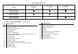
Swivel Bracket model chart
MODEL
BULL SHARK
40 XS
BULL SHARK
50
TIGER SHARK
80
SWIVEL BRACKET
SHOCK ABSORBER
SWIVEL BRACKET
POWER TRIM GWO37
SWIVEL BRACKET
POWER TRIM GWO27
LOCATION OF MAIN COMPONENTS Picture No. 12
N° DESCRIPTION
1 Hood
2 Hood hook back lever
3 Motor oil tank access manifold
4 Hood hook front lever
5 Fuel connector
6 Remote Control Box wires
7 Holes to fix the motor at the transom (Models with Shock Absorber or Power Trim)
8 Wires to connect the battery
9 Gas control cable
10 Gear control cable
11 Plate to connect the steering
12 Trim switch on tray
13 Support to lift the motor on the right side
14 Shock Absorber control lever (Models with Shock Absorber)
15 Directional Skeg
16 Anticavitation plate
17 Gearbox oil-level hole
N° DESCRIPTION
18 Gearbox oil-drain hole
19 Water inlet for speed meter
20 Water inlet for cooling
21 Anodes
22 Propeller
23 Water inlet to clean the cooling circuits
24 Motor lift on the left side
25 Indicator tube for the cooling water
26 Motor data label
27 Tim-adjusting pin
28 Anti-tilt hook control lever