
Owner`s manual
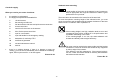

17
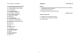
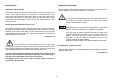
Connection from the side of the motor
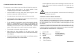
To connect the control cables to the motor follow the following instructions:
• Put the remote control lever in the neutral position. Lower
completely the gas control lever in neutral position
• Insert the cables in the tray, letting them pass through the holes
made on the right side of the fuel connector.
• Screw the remote control heads at the end of the two cables.
• Insert the heads in the pawls of the gears and accelerator levers,
paying attention not to muddle the cables.
• Fix the sheath of the accelerator control cable putting the sheath
retainer in correspondence of the groove of the sheath and
screwing it (using the two screws TC Phillips M5x20 and the two
self-locking nuts of the Kit K 44) in the holes made in vertical
position on the support of the remote control box sheath retainers.
• Fix the heads on the pawls using the split pins
• Make again the same operation for the gears control cable
screwing the bolt in correspondence of the holes made horizontally
on the support.
• The sheath retainer support must be fixed in two different positions
according to the length of the control cables.
Another adjustment can be made unscrewing the remote control box
heads. When you've finished the adjustment fix the heads with the
counter nuts.
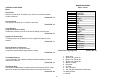
Picture No. 33
At the end of the operations control the correct functioning of
the remote control box.
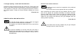
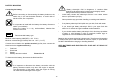
STEERING CONTROL DEVICE MOUNTING
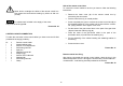
Insert the control cable in the tube brackets union.
Fix one extremity of the longitudinal rod of control of the steering to the
steering fixation plate, using the apposite nut, bolt and washer. Then fix
the other extremity of the rod to the cable of control through the nut and
the washers.
Insert the sheet-retainer 2 in the control cable. Insert the cable in the tube
brackets union, then on the cable itself and then the washer 4 and the ring
5. stop the sheet in the bracket tube screwing the rings 2 and 5 completely
(see the positions of the bolts shown in the picture).
1 Control cable 5 Ring nut
2 Ring 6 Control cable end
3 Tube bracket union 7 Steering link arm kit
4 Washer 8 Steering plate
A Steering plate
B Steering arm kit
C Control cable end
Picture No.34