MODEL: CB OPERATING INSTRUCTION AND PARTS MANUAL ■ CB-3010 ■ CB-3530 ■ CB-4020 For technical assistance or the SHARK dealer nearest you, call 1-800-771-1881 or visit our website at www.shark-pw.
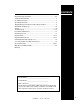
CONTENTS Important Safety Information ................................................................ 4-5 Component Identification ........................................................................ 6 Assembly Instructions ............................................................................. 7 Operating Instructions ............................................................................. 8 Applying Detergent and General Operating Techniques ..........................
PRESSURE WASHER OPERATOR’S MANUAL INTRODUCTION WARNING Thank you for purchasing this Pressure Washer. All information in this manual is based on the latest product information available at the time of printing. Manufacturer reserves the right to make changes at any time without incurring any obligation. Owner/User Responsibility: The owner and/or user must have an understanding of the manufacturer’s operating instructions and warnings before using this pressure washer.
OPERATOR’S MANUAL 21. Follow the maintenance instructions specified in the manual. PRESSURE WASHER 14. Inlet water must be no hotter then 190° and clean fresh water. It is recommended that inlet water temperatures not exceed 175° for pump longevity. 15. The best insurance against an accident is precaution and knowledge of the machine. 16. Manufacturer will not be liable for any changes made to our standard machines or any components not purchased from them. 17.
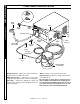
PRESSURE WASHER COMPONENT IDENTIFICATION High Pressure Nozzle Soap Nozzle Water Supply OPERATOR’S MANUAL Wand On/Off Switch Quick Coupler Garden Hose Inlet Spray Gun Discharge Nipple Garden Hose (not included) Trigger Swivel Connector Detergent Injector Hose Coupler Detergent Pick-up Tube High Pressure Hose Detergent Bucket (not included) Detergent Injector - Allows you to siphon and mix detergents, when used with soap nozzle.
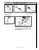
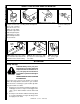
Spray Gun Nozzle Coupler Safety Latch High Pressure Hose STEP 2: Insert nozzle into coupler. STEP 3: Release the coupler collar and push the nozzle until the collar clicks. Pull the nozzle to make sure it is seated properly. Inlet Fitting STEP 4: Connect garden hose to the cold water source. OPERATOR’S MANUAL STEP 1: Attach the high pressure hose to the spray gun using teflon tape on hose threads. Use safety latch to prevent from opening.
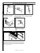
PRESSURE WASHER OPERATING INSTRUCTIONS Cold Water Source OPERATOR’S MANUAL Garden Hose STEP 1: Connect garden hose to the cold water source and turn water on completely. Never use hot water. STEP 2: Trigger the spray gun to eliminate trapped air then wait for a steady flow of water to emerge from the spray nozzle. Safety Latch STEP 4: Turn machine on by pushing switch at front of machine. WARNING! Never replace nozzles without engaging the safety latch on the spray gun trigger.
WARNING WARNING: Some detergents may be harmful if inhaled or ingested, causing severe nausea, fainting or poisoning. The harmful elements may cause property damage or severe injury. CLEANING TIPS Pre-rinse cleaning surface with fresh water. Place detergent suction tube directly into cleaning solution and apply to surface at low pressure (for best results, limit your work area to sections approximately 6 feet square and always apply detergent from bottom to top).
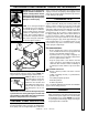
PRESSURE WASHER OPERATOR’S MANUAL SHUTTING DOWN AND CLEAN-UP STEP 1: Remove detergent suction tube from soap container and insert into one gallon of fresh water. Use black soap nozzle with detergent injector. Pull trigger on spray gun and siphon water for one minute. STEP 2: Turn off machine by STEP 3: Turn off water supply. pushing switch on front panel. Pump Water Inlet High Pressure Outlet STEP 5: Disconnect the garden hose from the water inlet on the machine. Protect from freezing.
PROBLEM POSSIBLE CAUSE SOLUTION PUMP RUNNING NORMALLY BUT PRESSURE LOW ON INSTALLATION Pump sucking air Check water supply and possibility of air seepage. Check valves sticking Check and clean or replace if necessary. Unloader valve seat faulty Check and replace if necessary. Nozzle incorrectlly sized Check and replace if necessary. Worn piston packing Check and replace if necessary. Valves worn Check and replace if necessary. Blockage in valve Check and clean out if necessary.
Troubleshooting Guide PRESSURE WASHER TROUBLESHOOTING PROBLEM POSSIBLE CAUSE SOLUTION PRESENCE OF WATER IN PUMP OIL Oil seal worn Check and replace if necessary. High humidity in air Check and change oil twice as often. Piston packing worn Check and replace if necessary. Piston packing worn Check and replace if necessary. O-Ring plunger retainer worn Check and replace if necessary. Oil seal worn Check and replace if necessary.
PREVENTATIVE MAINTENANCE This pressure washer was produced with the best available materials and quality craftsmanship. However, you as the owner, have certain responsibilities for the correct care of the equipment. Attention to regular preventative maintenance procedure will assist in preserving the performance of your equipment. Contact your dealer for maintenance. Regular preventative maintenance will add many hours to the life of your pressure washer.
PRESSURE WASHER EXPLODED VIEW 10 63 7 Enlarged Reverse View 64 70 63 20 78 76 71 13 62 9 OPERATOR’S MANUAL 74 58 Time Delay Option 75 11 77 12 61 Auto Start Option 64 5 64 22 21 54 25 4 23 63 58 6 77 62 13 Auto Start Option 70 64 7 62 3 9 71 66 61 51 19 58 For Detail SeePump Assy. 1 64 74 76 75 22 2 12 25 3010D w/Time Delay Option 24 15 14 8 23 14 SHARK CB • 97-714 • REV.
PRESSURE WASHER EXPLODED VIEW 27 OPERATOR’S MANUAL 39 43 46 68 44 42 17 50 40 41 16 73 26 28 45 50 49 38 69 29 53 46 32 37 72 57 56 31 59 65 33 67 30 60 47 59 55 50 35 34 52 36 19 48 46 18 15 SHARK CB • 97-714 • REV.
PRESSURE WASHER OPERATOR’S MANUAL EXPLODED VIEW PARTS LIST ITEM PART NO.
ITEM PART NO. 38 11-0308 DESCRIPTION QTY Label, Control Panel (CB Models) 1 Label, Stripe, 29” (CB) 2 ITEM PART NO.
PRESSURE WASHER PUMP EXPLODED VIEW 2 14 1 3 4 10 9 2 Time Delay Shutdown Option 4 OPERATOR’S MANUAL 8 12 16 15 17 13 6 Auto Start/Stop Option 11 5 3 PUMP EXPLODED VIEW PARTS LIST ITEM PART NO. DESCRIPTION QTY 1 Unloader, See Specifications Pages 20-21 2 2-0053 Elbow, 1/2" JIC, 3/8", 90° (Auto Start/Stop Option) ITEM PART NO.
PRESSURE WASHER HOSE & SPRAY GUN ASSEMBLY 6 5 4 8 OPERATOR’S MANUAL 3 7 10 1 9 11 2 HOSE & SPRAY GUN ASSEMBLY PARTS LIST ITEM PART NO. 1 DESCRIPTION QTY 2-2002 Coupler, 3/8” Female 2-0121 Quick Coupler O-Ring ITEM PART NO. DESCRIPTION QTY Injector, Chemical Adj., 3-5 GPM 0.083 1 2-2000 2-0119 Coupler, 1/4” Female Quick Coupler O-Ring 1 1 9 4-02080000 Tube, 1/4” x 1/2” Clear Vinyl 6 ft.
PRESSURE WASHER Specifications SPECIFICATIONS Nozzle Pump Unloader Pump Pump Pulley Pump Par t No. Bushing Motor Motor Motor Model Size Pump Par t No. Par t No. Pulley Bushing Par t No. Size Voltage/ph Hz 301001D 5.5 T991 5-23020 5-3208 AK74H 5-40107401 24MM 5-512024 2HP 120V/1PH 60 402007A 06 GM4035HR 5-1922 5-3208 2AK74H 5-40207401 24MM 5-512024 6.2HP 230V/1PH 60 402007B 06 GM4035HR 5-1922 5-3208 2AK74H 5-40207401 24MM 5-512024 6.
Motor Pulley Motor Bushing Belt Belt Contactor Size Par t No. Overload Transformer Part No. Model Part No. Pulley Par t No. Bushing Part No. Par t No. Part No.
PRESSURE WASHER OPERATOR’S MANUAL MULTI-ROOM INSTALLATION 22 SHARK CB • 97-714 • REV.
WHAT THIS WARRANTY COVERS All SHARK PRESSURE WASHERS are warranted by SHARK to the original purchaser to be free from defects in materials and workmanship under normal use, for the periods specified below. This Limited Warranty is subject to the exclusions shown below, is calculated from the date of the original purchase, and applies to the original components only. Any parts replaced under this warranty will assume the remainder of the part’s warranty period.
Form #97-714 • Revised 4/05 • Printed in U.S.A.