® OPERATOR’S MANUAL MODEL # HD 2.8/10 ST Ed B / CB-301007D ORDER # 1.575-300.0 MODEL # HD 3.5/30 ST Ea B / CB-353007A ORDER # 1.575-306.0 HD 4.2/20 ST Ea B / CB-402007A 1.575-301.0 HD 3.5/30 ST Eb B / CB-353007B 1.575-307.0 HD 4.2/20 ST Eb B / CB-402007B 1.575-302.0 HD 3.5/30 ST Ec B / CB-353007C 1.575-308.0 HD 4.2/20 ST Ec B / CB-402007C 1.575-303.0 HD 3.5/30 ST Eg B / CB-353007G 1.575-309.0 HD 4.2/20 ST Eg B / CB-402007G 1.575-304.0 HD 3.5/30 ST Eh B / CB-353007H 1.575-310.0 HD 4.
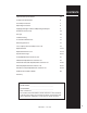
CONTENTS Important Safety Information 4-5 Component Identification 6 Assembly Instructions 7 Operating Instructions 8 Applying Detergent & General Operating Techniques 9 Shut Down & Clean-Up 10 Storage 10 Troubleshooting 11 Preventative Maintenance 12 Oil Change Record 12 Hose & Spray Gun Assembly & Parts List 13 Exploded View 14-15 Exploded View Parts List 16-19 Specifications Page 20-21 Pump Exploded View and Parts List 22 VB8 Valve Exploded View and Parts List 23 AR/AL 607
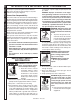
PRESSURE WASHER OPERATOR’S MANUAL INTRODUCTION & Important Safety Information Thank you for purchasing this Pressure Washer. We reserve the right to make changes at any time without incurring any obligation. Owner/User Responsibility: The owner and/or user must have an understanding of the manufacturer’s operating instructions and warnings before using this pressure washer. Warning information should be emphasized and understood.
PRESSURE WASHER WARNING: Grip cleaning wand securely with both hands before starting. Failure to do this could result in injury from a whipping wand. Trigger Gun Kicks back - Hold with both hands 14. Inlet water must be clean fresh water and no hotter then 90°F. 15. Manufacturer will not be liable for any changes made to our standard machines or any components not purchased from us. 16. The best insurance against an accident is precaution and knowledge of the machine.
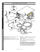
PRESSURE WASHER OPERATOR’S MANUAL Component Identification High Pressure Nozzle Soap Nozzle Water Supply Wand On/Off Switch Quick Coupler Garden Hose Inlet Spray Gun Discharge Nipple Garden Hose (not included) Trigger Swivel Connector Detergent Injector Hose Coupler Detergent Pick-up Tube High Pressure Hose Detergent Bucket (not included) Detergent Injector - Allows you to siphon and mix detergents, when used with soap nozzle.
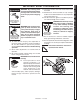
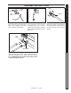
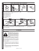
PRESSURE WASHER Safety Latch Coupler High Pressure Hose STEP 1: Attach the high pressure hose to the spray gun using teflon tape on hose threads. Use safety latch to prevent from opening. STEP 2: Connect garden hose to the cold water source. Before installing nozzle, turn on water supply and run machine, allowing water to flush through the system until clear. STEP 3: Insert nozzle into coupler. Release the coupler collar and push the nozzle until the collar clicks.
OPERATOR’S MANUAL PRESSURE WASHER Operating Instructions Cold Water Source Garden Hose STEP 1: Connect garden hose to the cold water source and turn water on completely. Never use hot water. STEP 2: Trigger the spray gun to eliminate trapped air then wait for a steady flow of water to emerge from the spray wand. Then install nozzle. On/Off Switch Safety Latch STEP 4: Turn machine on by pushing switch at front of machine.
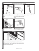
WARNING: Some detergents may be harmful if inhaled or ingested, causing severe nausea, fainting or poisoning. The harmful elements may cause property damage or severe injury. OPERATOR’S MANUAL STEP 1: Use detergent designed specifically for pressure washers. Household detergents could damage the pump. Prepare detergent solution as required by the manufacturer. Fill a container with pressure washer detergent. Place the filter end of detergent suction tube into the detergent container.
OPERATOR’S MANUAL PRESSURE WASHER shutting down and clean-up STEP 1: Remove detergent suction tube from soap container and insert into one gallon of fresh water. Use black soap nozzle with detergent injector. Pull trigger on spray gun and siphon water for one minute. STEP 2: Turn off machine by pushing switch on front panel. Pump Water Inlet STEP 3: Turn off water supply. STEP 4: Press trigger to release water pressure.
PROBLEM POSSIBLE CAUSE SOLUTION PUMP RUNNING NORMALLY BUT PRESSURE LOW ON INSTALLATION Pump sucking air Check water supply and possibility of air. Check valves sticking Check and clean or replace if necessary. Unloader valve seat faulty Check and replace if necessary. Nozzle incorrectly sized Check and replace if necessary. Worn piston packing Check and replace if necessary. Valves worn Check and replace if necessary. Blockage in valve Check and clean if necessary.
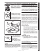
PRESSURE WASHER OPERATOR’S MANUAL Preventative Maintenance Preventative Maintenance This pressure washer was produced with the best available materials and quality craftsmanship. However, you as the owner, have certain responsibilities for the correct care of the equipment. Attention to regular preventative maintenance procedure will assist in preserving the performance of your equipment. Contact your dealer for maintenance.
PRESSURE WASHER Hose & Spray Gun Assembly 8 4 OPERATOR’S MANUAL PRESSURE WASHER 6 3 5 7 10 1 OPERATOR’S MANUAL 9 11 2 Hose & Spray Gun Assembly Parts List ITEM PART NO. DESCRIPTION QTY 1 9.802-166.0 Coupler, 3/8" Female 1 9.802-100.0 Quick Coupler O-Ring 1 2 8.739-125.0 Hose, 3/8" x 50', 1 Wire Tuff-Flex 1 3 8.711-348.0 Spray Gun 1 4 9.802-219.0 Wand w/Side Grip 1 5 8.712-398.0 Nozzle, Soap, Brass 1 6 Nozzle, See Exploded View Parts List 7 9.
PRESSURE WASHER Exploded View 10 Enlarged Reverse View 64 63 7 71 13 63 20 78 76 62 9 OPERATOR’S MANUAL 74 58 Time Delay Option 75 11 77 Auto Start Option 61 64 63 64 5 54 23 58 6 62 13 64 7 12 25 4 77 Auto Start Option 22 21 70 62 9 3 71 66 61 51 19 58 For Detail See Pump Assy. 1 64 76 75 74 2 12 22 25 1.575-300.0 24 15 8 14 23 14 9.800-086.0 • Rev.
PRESSURE WASHER Exploded View OPERATOR’S MANUAL PRESSURE WASHER 27 39 OPERATOR’S MANUAL 43 68 44 17 50 40 41 16 42 46 79 73 26 28 45 50 49 38 69 29 53 46 32 37 72 57 56 31 59 65 33 67 30 60 47 59 55 78 35 36 34 52 19 50 48 46 18 15 9.800-086.0 • Rev.
PRESSURE WASHER OPERATOR’S MANUAL Exploded View Parts List ITEM PART NO. DESCRIPTION QTY 1 Unloader, See Specifications Pages 2 Pump, See Specifications Pages 3 Motor, See Specifications Pages 4 9.802-551.0 9.804-556.0 Transformer (301.0, 302.0, 303.0, 306.0, 307.0, 308.0) Transformer (304.0, 305.0, 309.0, 310.0) 1 1 5 8.933-007.0 Fuse, ATMR, 1 Amp, 600V (306.0, 307.0, 310.0, 301.0, 302.0, 304.0, 305.0) 2 9.802-462.0 Fuse, 1/2 Amp, 600V (303.0, 308.0) 2 6 9.802-463.
PRESSURE WASHER PART NO. DESCRIPTION QTY 24 9.802-039.0 Elbow, 1/2" JIC x 3/8", 90° 1 25 9.802-436.0 Cord, Serv, SEO, 10/3 Coleman, Motor (301.0, 304.0) 3.33 ft. 9.802-437.0 Cord Service, 10/4, Motor (310.0) 3.33 ft. 9.802-428.0 Cord, Service, 12/3, Motor (300.0) 4.25 ft. 9.802-425.0 Cord, Service, 8/3, Motor (306.0, 309.0) 3.33 ft. 9.802-429.0 Cord Service, 12/4, Motor (302.0, 303.0, 305.0, 307.0, 308.0) 3.33 ft. 26 9.800-016.
PRESSURE WASHER OPERATOR’S MANUAL Exploded View Parts List ITEM PART NO. DESCRIPTION QTY 45 9.802-522.0 Strain Relief, 1" 1 46 9.802-765.0 Screw, 1/4" x 1/2", BH SOC CS 14 47 9.802-817.0 Washer, 3/8" x 1" Steel 4 48 9.802-710.0 Bolt, 5/16" x 1 NC (300.0) 4 9.802-720.0 Bolt, 3/8" x 1" NC, HH (301.0, 302.0, 303.0, 304.0, 305.0, 306.0, 307.0, 308.0, 309.0, 310.0) 4 49 9.800-034.0 Label, Clear Lexan, 2-1/4" x 4-1/2" 1 50 9.802-073.0 Weather Stripping 7 ft.
PART NO. DESCRIPTION QTY 70 9.802-514.0 Strain Relief, Small, LQ Tite (Time Delay/Auto-Start Option) 1 9.802-524.0 ▲ Lock-Nut, 1/2" Conduit (Time Delay/Auto-Start Option) 1 71 9.802-423.0 Cord, Service, SEO, 16/3 2.5 ft. 9.802-424.0 Cord, Service, SEO 16/4 (Time Delay Shutdown Option) 2.5 ft. 72 9.802-779.0 Nut, 3/8" ESNA 4 73 8.718-980.0 Washer, 5/16" Flat 4 74 9.802-467.0 Base Relay (Time Delay Shutdown Option) 1 75 9.802-468.
PRESSURE WASHER Specifications Specifications Pump Pump Part No. Pump Pulley Pump Pulley Part No. Pump Bushing Bushing Part No. 1.575-300.0 KD3030R.1 1.575-301.0 KM4035R.2 9.804-006.0 AK74H 9.802-369.0 24MM 9.802-343.0 2AK74H 9.802-369.0 24MM 1.575-302.0 1.575-303.0 KM4035R.2 9.802-343.0 2AK74H 9.802-369.0 KM4035R.2 9.802-343.0 2AK74H 9.802-369.0 1.575-304.0 KM4035R.2 9.802-343.0 2AK74H 1.575-305.0 KM4035R.2 9.802-343.0 2AK74H 1.575-306.0 KM4035R.2 9.802-343.0 1.
Model Motor Part No. Motor Pulley Motor Pulley Part No. 300.0 9.802-339.0 AK32x5/8 9.804-004.0 301.0 9.802-336.0 2AK56H 9.802.373.0 302.0 9.802-329.0 2AK56H 9.802-373.0 303.0 9.802-329.0 2AK56H 9.802-373.0 304.0 9.802-337.0 2AK56H 9.802-373.0 305.0 9.802-330.0 2AK56H 9.802-373.0 306.0 8.715-097.0 2BK52H 307.0 8.715-105.0 308.0 8.715-105.0 309.0 310.0 Motor Bushing Motor Part No. Belt Size Belt Part No. Contractor Part No. Overload Part No.
OPERATOR’S MANUAL PRESSURE WASHER Pump Exploded View 2 3 14 10 1 4 2 9 Time Delay Shutdown Option 4 6 12 16 13 5 8 Auto Start/Stop Option 15 11 3 17 Pump Exploded View Parts List ITEM PART NO. DESCRIPTION QTY 1 8.715-483.0 Unloader, AL-VRT, 7.8 GPM @ 4200 PSI 1 2 9.802-039.0 Elbow, 1/2" JIC, 3/8", 90° 1 3 9.802-048.0 Swivel, 1/2" JIC x 3/8" Male 1 4 9.802-129.0 Elbow, 1/2" JIC x 3/8" 1 5 8.706-790.0 Nipple, 1/2" Close 1 6 8.706-844.
5-3027 2 30 27 28 29 16 25 37 15 32 11 PRESSURE WASHER 31 27 26 12 10 24 9 23 OPERATOR’S MANUAL OPERATOR’S MANUAL PRESSURE WASHER VB8 Unloader Valve exploded view 39 13 6 22 14 8 13 21 5 7 20 38 40 36 18 4 35 19 17 34 33 3 2 1 VB8 Unloader Valve exploded view parts list ITEM PART NO. DESCRIPTION QTY ITEM PART NO. DESCRIPTION QTY 1 60.0058.31 3/8 Bsp F Outlet Fitting 1 22 60.1210.31 Upper Frame 1 2 10.3070.02* O-ring 1.78 x 18.77 mm 2 23 14.7421.
AR - AL 607 #9.802-367.0 7-8 Gpm, 4200 Psi 7 OPERATOR’S MANUAL PRESSURE WASHER AR-AL Unloader exploded view and parts list 25 11 8 15 2 12 13 9 10 14 16 17 16 19 18 6 4 3 26 5 27 20 21 6 22 2 23 1 2 24 26 24 9.800-086.0 • Rev.
PRESSURE WASHER PART NO. DESCRIPTION QTY 1 83-005150010 Check Connector 1 2 83-005060108 ‡ O-Ring 2068 3 83-005100002 4 83-004120000 5 ITEM PART NO.
9.803-417.0 KD 3025.1 9.804-006.0 KD 3030.1 9.804-019.0 KD 4020.1 OPERATOR’S MANUAL PRESSURE WASHER KD.1 Pump exploded view TORQUE SPECS Item # Ft.-lbs 14 65 17 18 25 7.6 34 7 44 13 KD.1 Pump exploded view parts list item Part no. Description QTY item Part no. Description QTY 1 9.803-938.0 Crankcase 1 11* See Kits O-Ring Ø1.78 x 15.54 6 2* See Kits Plunger Oil Seal 3 12* See Kits Valve Assembly 6 3* See Kits O-Ring Ø1.78 x 28.30 3 13* See Kits O-Ring Ø2.62 x 18.
PRESSURE WASHER Description QTY 33 8.933-010.0 Crankshaft Seal 1 34* See Kits Plunger Nut 3 35* See Kits Copper Spacer 3 36* See Kits Plunger, 15mm (3030) 3 See Kits Plunger, 18mm (4020, 3025) 3 37* See Kits Copper Spacer 3 38* See Kits O-Ring Ø1.78 x 5.28 3 39* See Kits Teflon Ring 3 40* See Kits Plunger Rod 3 41 9.803-965.0 Connecting Rod Pin 3 42 9.803-966.0 Connecting Rod 3 43 9.803-218.0 Spring Washer 6 44 8.933-020.0 Connecting Rod Screw 6 45 9.
8.904-689.0 KM3540R.2 9.803-405.0 KM4030R.2 9.803-406.0 KM4030L.2 9.802-343.0 KM4035R.2 9.803-407.0 KM4035L.2 9.802-342.0 KM5030R.2 9.803-408.0 KM5030L.2 OPERATOR’S MANUAL PRESSURE WASHER KM.2 Pump exploded view TORQUE SPECS Item # Ft.-lbs 17 75 18 30 26 8 36 7 47 13 52 7.6 KM.2 Pump exploded view parts list ITEM PART NO. 1 8.933-012.0 DESCRIPTION QTY Crankcase ITEM PART NO. DESCRIPTION QTY 1 26 9.802-944.0 Hexagonal Screw 8 2 9.803-196.0 Plunger Guide 3 27 8.717-210.
PRESSURE WASHER DESCRIPTION QTY 42 9.803-144.0 Plunger Rod 3 43 9.803-158.0 Connecting Rod 3 44 9.802-913.0 Snap Ring 6 45 9.802-916.0 Connecting Rod Pin 3 46 9.803-218.0 Spring Washer 6 47 9.803-238.0 Connecting Rod Screw 6 48 8.933-016.0 O-Ring, Ø2.62 x 126.67 1 49 9.803-165.0 Crankcase Cover 1 50 9.803-197.0 O-Ring, Ø1.78 x 14 1 51 9.803-202.0 Sight Glass 3/4 1 52 9.802-939.0 Cover Screw 5 OPERATOR’S MANUAL OPERATOR’S MANUAL ITEM PART NO.
PRESSURE WASHER OPERATOR’S MANUAL Multi-Room Installation 30 9.800-086.0 • Rev.
PRESSURE WASHER OPERATOR’S MANUAL Phone: 360-833-1600 fax: 800-248-8409 www.karchercommercial.us WHAT THIS WARRANTY COVERS All Kärcher commercial pressure washers are warranted by Kärcher to the original purchaser to be free from defects in materials and workmanship under normal use, for the periods specified below. This Limited Warranty, subject to the exclusions shown below, is calculated from the date of the original purchase, and applies to the original components only.
® www.karchercommercial.com www.karchershark.com Form # 9.800-086.0 • Revised 3/09 • Printed in U.S.A.