SSD DIESEL OPERATOR’S MANUAL ■ SSD-503067E/G For technical assistance or the SHARK dealer nearest you visit our website at www.shark-pw.
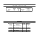
MACHINE SPECIFICATIONS Machine 503067E/G Volume at Pump Head (GPM) Pressure at Pump Head (PSI) Weight (Lbs) Dimensions Length x Width x Height (Inches) 5.2 3000 1066 51" x 44" x 41" OPTIONS Part No.
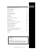
CONTENTS Introduction and Important Safety Information 4-5 Component Identification 6 Assembly Instruction 7 Operating Instructions 8-9 Detergents and Cleaning Tips 10 Shut Down and Clean-Up 11 Maintenance 12-14 Troubleshooting 15-18 Maintenance and Oil Change Chart 19 Exploded View 20-21 Exploded View, Parts List 22-24 Platform, Isolator, Exploded View and Parts List 25 Pump Assemblies, Exploded View 26 Pump Assemblies, Parts List 27 Control Panel, Exploded View 28 Control Pan
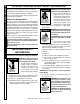
PRESSURE WASHER OPERATOR’S MANUAL INTRODUCTION & IMPORTANT SAFETY INFORMATION Thank you for purchasing a diesel pressure washer. All information in this manual is based on the latest product information available at the time of printing. We reserve the right to make changes at any time without incurring any obligation. Owner/User Responsibility: The owner and/or user must have an understanding of the manufacturer’s operating instructions and warnings before using this pressure washer.
8. High pressure developed by these machines will cause personal injury or equipment damage. Use caution when operating. Do not direct discharge stream at people, or severe injury or death will result. WARNING 9. Eye safety devices, safety clothing, hand and foot protection must be worn when using this equipment. 10. Never make adjustments on machine while it is in operation. WARNING: Spray gun kicks back. Hold with both hands. 11. Grip cleaning wand securely with both hands before starting the cleaner.
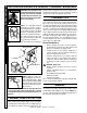
PRESSURE WASHER OPERATOR’S MANUAL COMPONENT IDENTIFICATION Inlet Connection Flue Adapter Optional 7-10049 Water Supply Hose (not included) Insulation Gasket Optional 7-01471 Note: Burner air adjustment must be tested after installation.
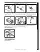
Spray Gun Pressure Nozzle Pressure Nozzle Wand Coupler Wand Coupler Safety Latch Wand Collar STEP 1: Attach the high pressure hose to the spray gun using teflon tape on hose threads. DipStick STEP 2: Pull the spring-loaded collar of the wand coupler back to insert your choice of pressure nozzle. Coupler Collar STEP 3: Release the coupler collar and push the nozzle until the collar clicks. Pull the nozzle to make sure it is seated properly.
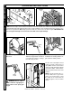
PRESSURE WASHER OPERATOR’S MANUAL OPERATING INSTRUCTIONS Oil Filler Cap Oil Dipstick STEP 1: Check engine oil level. Oil level should be level with the bottom of the oil filler neck. (Refer to the engine's operating manual included with machine.) We recommend that the oil be changed after the first 5 hours of use, then once every 50 hours. Note: Improper oil levels will cause low oil sensor to shut off engine. IMPORTANT! Do not run engine with high or low oil levels as this will cause engine damage.
Steam Valve Burner Switch Thermostat This lowers the pressure and raises the temperature. Step 2: Turn the thermostat knob to the 270° mark, (The thermostat is a high limit device and does not regulate temperature. Step 3: To stop, reverse steps and set all controls to their original settings. Step 4: Turn burner switch off, open trigger on spray gun and allow water to cool. OPERATOR’S MANUAL Step 1: For steam, open the steam valve counterclockwise.
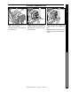
WARNING WARNING: Some detergents may be harmful if inhaled or ingested, causing severe nausea, fainting or poisoning. The harmful elements may cause property damage or severe injury. STEP 1: Use detergent designed specifically for pressure washers. Household detergents could damage the pump. Prepare detergent solution as required by the manufacturer. Fill a container with pressure washer detergent. Place the filter end of detergent suction tube into the detergent container.
Engine On-Off Switch STEP 2: Read engine operator manual. STEP 3: Turn off water supply. OPERATOR’S MANUAL STEP 1: Remove detergent suction tube from container and insert into one gallon of fresh water. Open detergent mixing valve. Pull trigger on spray gun and siphon water for one minute. PRESSURE WASHER SHUTTING DOWN AND CLEAN-UP Pump Discharge Fitting Water Inlet Safety Latch STEP 4: Press trigger to release water pressure. STEP 5: Disconnect the garden hose from the water inlet on the machine.
PRESSURE WASHER OPERATOR’S MANUAL MAINTENANCE PREVENTATIVE MAINTENANCE 1. Check to see that water pump is properly lubricated. 2. Follow winterizing instructions to prevent freeze damage to pump and coils. 3. Always neutralize and flush detergent from system after use. 4. If water is known to have high mineral content, use a water softener in your water system, or de-scale as needed. 5. Do not allow acidic, caustic or abrasive fluids to be pumped through system. 6.
Removal of Soot from Heating Coil: Electrode Setting: Beckett Electrodes In the heating process, fuel residue in the form of soot deposits may develop between the heating coil pipes, and block air flow which will affect burner combustion. When soot has been detected on visual observation, the soot on the coil must be washed off after following the coil removal steps (See Coil Removal on page 14).
PRESSURE WASHER OPERATOR’S MANUAL MAINTENANCE Coil Removal: Removal of coil because of freeze breakage, or to clean soot from it can be done quickly and easily. 1. Disconnect hose from pump to inlet side of the coil. 2. Carefully disconnect the thermostat sensor making sure you do not crimp the capillary tube. 3. Remove burner assembly from combustion chamber. 4. Remove the 3-3/8" bolts from each side of coil and tank assembly (these bolts are used to fasten tank to chassis). 5.
PROBLEM POSSIBLE CAUSE SOLUTION LOW OPERATING PRESSURE Faulty pressure gauge Install new gauge. Insufficient water supply Use larger supply hose; clean filter at water inlet. Old, worn or incorrect spray nozzle Match nozzle number to machine and/or replace with new nozzle. Belt slippage Tighten or replace; use correct belt. Plumbing or hose leak Check plumbing system for leaks. Retape leaks with teflon tape. Faulty or misadjusted unloader valve Adjust unloader for proper pressure.
PROBLEM POSSIBLE CAUSE SOLUTION BURNER WILL NOT LIGHT (continued from previous page) Flex coupling slipping on fuel pump shaft or burner motor shaft Replace if needed. On-Off switch defective Check for electrical current reaching burner assembly with burner switch on. Heavy sooting on coil and burner can cause interruption of air flow and shorting of electrodes Clean as required. Improper electrode setting Check and reset according to diagram in Operator's Manual.
PROBLEM POSSIBLE CAUSE SOLUTION LOW WATER TEMPERATURE Improper fuel or water in fuel Replace with clean and proper fuel. Low fuel pressure Increase fuel pressure. Weak fuel pump Check fuel pump pressure. Replace pump if needed. Fuel filter partially clogged Replace as needed. Soot build-up on coils not allowing heat transfer Clean coils. Improper burner nozzle See burner specifications (page 34). Incoming water to machine warm or hot Lower incoming water temperature.
Troubleshooting Guide PRESSURE WASHER TROUBLESHOOTING PROBLEM POSSIBLE CAUSE SOLUTION OIL DRIPPING Oil seal worn Check and replace if necessary. EXCESSIVE VIBRATION IN DELIVERY LINE Irregular functioning of the valves Check and replace if necessary. DETERGENT NOT DRAWING Air leak Tighten all clamps. Check detergent lines for holes. Restrictor in float tank is missing Replace restrictor. Check for proper orifice in restrictor. Filter screen on detergent suction hose plugged Clean or replace.
This pressure washer was produced with the best available materials and quality craftsmanship. However, you as the owner have certain responsibilities for the correct care of the equipment. Attention to regular preventative maintenance procedures will assist in preserving the performance of your equipment. Contact your dealer for maintenance. Regular preventative maintenance will add many hours to the life of your pressure washer. Perform maintenance more often under severe conditions.
PRESSURE WASHER EXPLODED VIEW B04 B05 P31 G32 G03 G02 G30, G31 P32 B01 B03 P30 E05 G00 OPERATOR’S MANUAL E04 B02 B00 L06 L08 L04 L00 L06 L02 L01 L05 Fuel Lines to Engine (Reversed View Of Label) L05 R101 R103 R071 X05 L03 X01 R100 X03 X00 R106 R070 X04 R105A R105B R105C R104 R105D X03 F00 X02 For Detail See Float Tank Illus.
PRESSURE WASHER EXPLODED VIEW C301 R102 OPERATOR’S MANUAL C23 C21 C34 C33 C35 C22 C17 C00 C31 C16 C32 C30 C31 C18 E27 C15 E002 Fuel Lines To Burner H100,H101 H110,H111 C19 C05 S01 S04 Steam C20 H023,H024, H025 E00 H010,H011, H020,H021,H022 C19 C04 C02 C20 S03 C06 C09 C08 Fuel Lines To Fuel Tank C36 C10 E03 E02 C03 E20,E21,E22 C07 For E23,E24,E25 E09,E10, Detail See E251,E252 E11,E12, Control E13 Box Illus. E17 C01 H060 C11 E14 H030 H061 For Detail See Pump Assy. Illus.
PRESSURE WASHER OPERATOR’S MANUAL EXPLODED VIEW PARTS LIST ITEM QTY ITEM B00 PART NO. 95-07200077 Belt Guard, Diesel SS DESCRIPTION 1 C33 PART NO.
ITEM PART NO. DESCRIPTION QTY ITEM PART NO. DESCRIPTION QTY G01 90-1016 ▲ Bolt, 3/8" x 1", NC HH 4 H100 4-02100000 G02 90-4002 Washer, 3/8", SAE, Flat 8 Hose, 1/4", Push-On, Fuel Line 1.6 ft. G03 90-2002 Nut, 3/8", ESNA, NC 4 G10 95-07200009 Weldment, Pump/General Rail H101 2-9000 Clamp, Screw #4 H110 4-02100000 Hose, 1/4", Push-On, Fuel Line 1 2.1 ft. 90-1016 ▲ Bolt, 3/8" x 1", NC HH 3 H111 G12 2-011981 ▲ Washer, Snubbing 3 L00 95-07200081 Fuel Tank Assy, 20 Gal.
PRESSURE WASHER OPERATOR’S MANUAL EXPLODED VIEW PARTS LIST ITEM PART NO. ITEM PART NO. DESCRIPTION U022 90-4002 Washer, 3/8", SAE, Flat 2 U023 90-2002 Nut, 3/8" ESNA, NC 2 W00 95-07200076 Assy, Power Platform, Diesel 1 X00 2-0115 Box, Battery, M100 1 1 X01 90-1002 Bolt, 1/4" x 1", Hex Head 4 9.800-049.
PRESSURE WASHER PLATFORM ISOLATOR EXPLODED VIEW W11 W06 W08 W10 W12 W13 OPERATOR’S MANUAL W07 W05 W06 W06 W01 W09 W06 W09 W05 W06 W07 W05 W06 W08 W11 W09 W13 W14 PLATFORM ISOLATOR PARTS LIST PART NO.
PRESSURE WASHER OPERATOR’S MANUAL PUMP ASSEMBLIES EXPLODED VIEW Standard Pump Assembly H090 U051 U05 U09 U01 U07 H080 U08 H081 U04 U021 U03 P08 U02 H030 P01 P07 U031 P06 P05 Steam Option Pump Assembly P02 H090 P04 P09 U051 P03 P013 U05 P012 P011 U09 U01 U07 U08 H080 U04 U021 U03 P16 U02 P12 H030 P01 U031 P11 P13 P05 P14 P02 P04 P15 P09 P10 P013 P012 P03 P15 LEGEND 26 G = Generator R = Controls E = Engine N = Final Assembly L = Fuel Tank F = Frame X = Battery Box T = F
ITEM PART NO. DESCRIPTION QTY ITEM PART NO. DESCRIPTION H030 4-02047762 Hose, 3/8" Pressure 5 ft. P11 2-1089 H080 4-02100000 Hose, 1/2" Push-On 1.6 ft.
PRESSURE WASHER OPERATOR’S MANUAL CONTROL BOX EXPLODED VIEW R012 R015 R010 R011 R030 R020 R023 R021 R060 R022 R040 R050 28 SHARK SSD DIESEL • #97-6167 • REV.
ITEM PART NO. DESCRIPTION QTY ITEM PART NO.
PRESSURE WASHER FLOAT TANK ASSEMBLY T01 T00 OPERATOR’S MANUAL T09 T07 T10 T12 T08 T03 T02 T11 T06 T04 T05 To Pump FLOAT TANK PARTS LIST ITEM PART NO. DESCRIPTION QTY ITEM PART NO.
PRESSURE WASHER HOSE & SPRAY GUN ASSEMBLY 4 3 OPERATOR’S MANUAL 2 1 HOSE & SPRAY GUN PARTS LIST ITEM PART NO. DESCRIPTION 1 4-020750C Hose, 50' x 3/8", 2 Wire, TUFF Flex QTY ITEM 4 1 PART NO. DESCRIPTION 2-2000 Coupler, 1/4" QTY 1 2-20023 Coupler, 1/4" Female 1 2 4-01246 Spray Gun, Shut-Off, AP 1000 1 2-0003 ▲ Nipple, 1/4" Steel 1 3 4-0111021 Lance, Spray, Insulated, 35.
PRESSURE WASHER Specifications SPECIFICATIONS PART SPECIFICATIONS PUMP Machine Pump Model Model ENGINE Pulley Part # 503067E/GGT-4035 5-1924 Unloader 5-3208 Pulley Part # Bushing Bushing Part # 2BK90H5-40509001 25MM 5-512025 Engine Size 15 HP 32 SHARK SSD DIESEL • #97-6167 • REV.
GENERATOR ENGINE (CON'T) Model Bushing (Con't) Part # 503067E/G 5-531114 Belt Belt Pulley Belt Size Part # Pulley Part# Belts Part # Bushing BX 34 5-604034 BK 32H 5-40403201 BX22 5-604022 5-511063 PRESSURE WASHER Specifications SPECIFICATIONS 33 SHARK SSD DIESEL • #97-6167 • REV.
PRESSURE WASHER Specifications SPECIFICATIONS BECKETT BURNER SPECIFICATIONS Model No. SSD-503067E/G Burner Assy No. Fuel Nozzle Transformer 7-00011 7-01284 7-51824 Burner Motor 7-21344U Fuel Pump/ Solenoid/Cord Fuel Solenoid Coil Electrode 7-21844U 7-21755U 7-578703 34 SHARK SSD DIESEL • #97-6167 • REV.
WHAT THIS WARRANTY COVERS All SHARK PRESSURE WASHERS are warranted by SHARK to the original purchaser to be free from defects in materials and workmanship under normal use, for the periods specified below. This Limited Warranty is subject to the exclusions shown below, is calculated from the date of the original purchase, and applies to the original components only. Any parts replaced under this warranty will assume the remainder of the part’s warranty period.
Form #97-6167 • Revised 7/05 • Printed in U.S.A.