SSG OPERATOR’S MANUAL For technical assistance or the SHARK dealer nearest you visit our website at www.shark-pw.com #8.914-337.
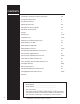
CONTENTS Introduction and Important Safety Information 3-5 Component Identification 6 Assembly Instructions 7 Operating Instructions 8-9 Detergents and Clean Up Tips 10 Shut Down and Clean-Up 11 Storage 11 Maintenance 12-14 Troubleshooting 15-18 Maintenance and Oil Change Charts 19 Exploded View, Left Side 20 Exploded View, Right Side 21 Exploded View, Parts List 22-24 Steam Pump, Exploded View and Parts List 25 Control Panel, Exploded View 26 Control Panel, Exploded View Parts List 26-2
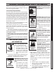
Thank you for purchasing this Pressure Washer. We reserve the right to make changes at any time without incurring any obligation. WARNING WARNING:This machine exceeds 85 db appropriate ear protection must be worn. Owner/User Responsibility: Owner and/or user must study and maintain for future reference the manufacturers’ instructions. The operator must know how to stop the machine quickly and understand the operation of all controls. Never permit anyone to operate the engine without proper instructions.
PRESSURE WASHER OPERATOR’S MANUAL Important Safety Information In an overfilling situation, additional precautions are necessary to ensure that the situation is handled in a safe manner. WARNING: Risk of injury. Disconnect battery ground terminal before servicing. 8. When in use , do not place machine near flammable objects as the engine is hot. 9. Oil burning appliances shall be installed only in locations where combustible dusts and flammable gases or vapors are not present.
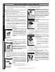
OPERATOR’S MANUAL 21. Do not allow acids, caustic or abrasive fluids to pass through the pump. 22. Never run pump dry or leave spray gun closed longer than 1-2 minutes. 23. Machines with shut-off spray gun should not be operated with the spray gun in the off position for extensive periods of time as this may cause damage to the pump. 24. Protect discharge hose from vehicle traffic and sharp objects. Inspect condition of high pressure hose before using or bodily injury may result. 25.
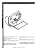
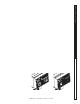
PRESSURE WASHER OPERATOR’S MANUAL Component Identification Small Pump — Delivers a specific gpm to the high pressure nozzle which develops pressure. Starter Grip— Used for starting the engine manually (except 20 HP Honda). Spray Gun — Controls the application of water and detergent onto cleaning surface with trigger device. Includes safety latch. Unloader Valve— Safety device which allows pressure to be released when spray gun is closed. Wand — Must be connected to the spray gun.
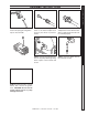
STEP 2: Pull the spring-loaded collar of the wand coupler back to insert your choice of pressure nozzle. STEP 3: Release the coupler collar and push the nozzle until the collar clicks. Pull the nozzle to make sure it is seated properly. STEP 5: Connect the high pressure hose to the pump discharge fitting. Push coupler collar forward until secure. STEP 6: Connect garden hose to the cold water source.
PRESSURE WASHER OPERATOR’S MANUAL SHARK SSG • 8.914-337.0 / 97-6134 • Rev.
PRESSURE WASHER OPERATOR’S MANUAL SHARK SSG • 8.914-337.0 / 97-6134 • Rev.
PRESSURE WASHER OPERATOR’S MANUAL WARNING: Some detergents may be harmful if inhaled or ingested, causing severe nausea, fainting or poisoning. The harmful elements may cause 10 SHARK SSG • 8.914-337.0 / 97-6134 • Rev.
PRESSURE WASHER shutting down and clean-up OPERATOR’S MANUAL STORAGE CAUTION: Always store your pressure washer in a location where the temperature will not fall below 32°F (0°C). The pump in this machine is susceptible to permanent damage if frozen. FREEZE DAMAGE IS NOT COVERED BY WARRANTY. 1. Stop the pressure washer, squeeze spray gun trigger to release pressure. 2. Detach water supply hose and high pressure hose. 3. Turn on the machine for a few seconds, until remaining water exits.
PRESSURE WASHER OPERATOR’S MANUAL Maintenance PREVENTATIVE MAINTENANCE 1. Check to see that water pump is properly lubricated. 2. Follow winterizing instructions to prevent freeze damage to pump and coils. 3. Always neutralize and flush detergent from system after use. 4. If water is known to have high mineral content, use a water softener in your water system, or de-scale as needed. 5. Do not allow acidic, caustic or abrasive fluids to be pumped through system. 6.
Step 4 After circulating solution, flush the entire system with fresh water. Clean out float tank and then reinstall wand assembly to spray gun. Removal of Soot from Heating Coil: Keep the tip free of surface deposits by wiping it with a clean, solvent saturated cloth, being careful not to plug or enlarge the nozzle. For maximum efficiency, replace the nozzle each season. Electrode Setting: Beckett Fuel: Use clean fuel oil that is not contaminated with water and debris.
PRESSURE WASHER OPERATOR’S MANUAL Maintenance Coil Removal: Removal of coil because of freeze breakage, or to clean soot from it can be done quickly and easily. 1. Disconnect hose from pump to inlet side of the coil. 2. Carefully disconnect the thermostat sensor making sure you do not crimp the capillary tube. 3. Remove burner assembly from combustion chamber. 4. Remove the 3-3/8" bolts from each side of coil and tank assembly (these bolts are used to fasten tank to chassis). 5.
PROBLEM POSSIBLE CAUSE SOLUTION LOW OPERATING PRESSURE Faulty pressure gauge Install new gauge. Insufficient water supply Use larger supply hose; clean filter at water inlet. Old, worn or incorrect spray nozzle Match nozzle number to machine and/or replace with new nozzle. Belt slippage Tighten or replace; use correct belt. Plumbing or hose leak Check plumbing system for leaks. Retape leaks with teflon tape. Faulty or misadjusted unloader valve Adjust unloader for proper pressure.
PROBLEM POSSIBLE CAUSE SOLUTION BURNER WILL NOT LIGHT (continued from previous page) Flex coupling slipping on fuel pump shaft or burner motor shaft Replace if needed. On-Off switch defective Check for electrical current reaching burner assembly with burner switch on. Heavy sooting on coil and burner can cause interruption of air flow and shorting of electrodes Clean as required. Improper electrode setting Check and reset according to diagram in Operator's Manual.
PROBLEM POSSIBLE CAUSE SOLUTION LOW WATER TEMPERATURE Improper fuel or water in fuel Replace with clean and proper fuel. Low fuel pressure Increase fuel pressure. Weak fuel pump Check fuel pump pressure. Replace pump if needed. Fuel filter partially clogged Replace as needed. Soot build-up on coils not allowing heat transfer Clean coils. Improper burner nozzle See burner specifications. Incoming water to machine warm or hot Lower incoming water temperature.
Troubleshooting Guide PRESSURE WASHER Troubleshooting PROBLEM POSSIBLE CAUSE SOLUTION OIL DRIPPING Oil seal worn Check and replace if necessary. EXCESSIVE VIBRATION IN DELIVERY LINE Irregular functioning of the valves Check and replace if necessary. DETERGENT NOT DRAWING Air leak Tighten all clamps. Check detergent lines for holes. Restricter in float tank is missing Replace restricter. Check for proper orifice in restricter. Filter screen on detergent suction hose plugged Clean or replace.
This pressure washer was produced with the best available materials and quality craftsmanship. However, you as the owner have certain responsibilities for the correct care of the equipment. Attention to regular preventative maintenance procedures will assist in preserving the performance of your equipment. Contact your dealer for maintenance. Regular preventative maintenance will add many hours to the life of your pressure washer. Perform maintenance more often under severe conditions.
PRESSURE WASHER OPERATOR’S MANUAL 21 SHARK SSG • 8.914-337.0 / 97-6134 • Rev.
PRESSURE WASHER OPERATOR’S MANUAL Exploded View Parts List ITEM PART NO. DESCRIPTION QTY 95-07200055 Coil, Rodless 1 2 95-07200010 2-01104 Top Wrap, SS ▲ Trim 1 6 ft.
ITEM PART NO.
PRESSURE WASHER OPERATOR’S MANUAL Exploded View Parts List DESCRIPTION QTY ITEM 85 2-9013 Clamp, 1/2" Ro-Clip 1 86 Hose, 1/2" Push-on 1 ft. 102 90-1034 ITEM PART NO. 4-02110000 PART NO. DESCRIPTION QTY Bolt, M6 x 1.0 12 x Metric 8.
PRESSURE WASHER Steam Pump Exploded View 2 3 IG H H ES PR R SU E M PU PS 4 OPERATOR’S MANUAL 9 11 5 6 1 11 7 To Detergent Valve 8 9 10 Steam Pump Parts List ITEM PART NO. 1 2-10630 2 2-0051 DESCRIPTION QTY Elbow, 3/4" JIC x 1/2" Male 1 ITEM PART NO.
OPERATOR’S MANUAL PRESSURE WASHER Control Panel Exploded View ITEM 1 PART NO. DESCRIPTION QTY 6-039144 Box, Plastic, Back 1 2 6-0391601 Box, Plastic, Front, Fabricated 1 3 4-05088 6-01270 Thermostat, 302°F 1 ▲ Conduit, Corrugated, 1/4" 3.3 ft 4 Bolt, 1/4" x 3/4" HH NC Nut, 1/4" Flange Zn 90-1001 90-200012 5 11-1047 11-1045 4 4 Decal, 12V Electrical Box 1 Decal, 120V Electrical Box (503027E/G, 503537E/G, 603537E/G) 1 26 SHARK SSG • 8.914-337.
ITEM ITEM 10 6-036711 2-90220 90-017 Relay, 24VDC, 40 Amp (503027E) 1 ▲ Mounting Tape, Square Backed 1 ▲ Nut 10/32 Keps 1 11 6-0611 90-1991 6-021595 Rectifier, Bridge (503027E) 1 Screw, 10/32" x 1/2" BH SOC Black 1 Din Rail (12 VDC) 4" 15 4-12806000 4-12806015 4-12806025 4-12806040 12 95-07200008 95-072000082 90-1994 2-01411 Weldment, Control Panel, Red 1 Weldment Control Panel, Black (503537E/G/Sun) 1 ▲ Screw, G
PRESSURE WASHER OPERATOR’S MANUAL Float Tank Exploded View 28 SHARK SSG • 8.914-337.0 / 97-6134 • Rev.
PRESSURE WASHER Hose & Spray Gun Exploded View OPERATOR’S MANUAL Hose & Spray Gun Parts List 29 SHARK SSG • 8.914-337.0 / 97-6134 • Rev.
PRESSURE WASHER Specifications Specifications parts SPECIFICATIONS: Shark pump PUMP Machine Pump Model Model 503027E Part Number Unloader Pulley ENGINE Pulley Part # Bushing Bushing Engine Engine Part # Size Part # Engine Pulley ST6035 5-1432 5-3208 2BK90H 5-4050900 25MM 5-512025 16 HP 5-0309 2BK34H 503027E/G ST6035 5-1432 5-3208 2BK90H 5-4050900 25MM 5-512025 16 HP 5-0309 3TB34 503537E/G ST6035 5-1432 5-3208 2BK100H 5-40510001 25MM 5-512025 20 HP 9.
ENGINE Pulley Model Part # Bushing CONTROLS Bushing Belt Part # Size Belt Pulley Part # Pulley Part # NA NA Belts Belt Part # Bushing 503027E 5-40503401 Hx1 5-511100 BX 43 5-604043 NA NA NA 503027E/G 5-407034 P2 X 1 5-531112 BX 43 5-604043 BK34H 5-4050340 BX32 5-604032 5-511063 503537E/G 5-407034 P2 X 1 5-531112 BX 44 5-604044 BK34H 5-4050340 BX34 5-604034 5-511063 603537E/G 5-407036 P2 X 1-1/8 5-531113 BX 44 5-604044 BK36H 5-4040360 BX34
PRESSURE WASHER Specifications Specifications BECKETT BURNER SPECIFICATIONS Burner Burner Fuel/Pump Fuel Model No. Assy No.
AR - AL 607 #9.802-367.0, 7-8 Gpm, 4200 Psi ITEM PART NO. DESCRIPTION QTY 8.718-371.0 Check Connector 1 9.804-536.0 ‡ O-Ring 2068 3 3 9.804-646.0 Shutter Spring 1 4 9.804-538.0 Shutter 1 5 9.804-539.0 ‡ O-Ring 631290 SH 1 6 83-005170102 1/4 G Plug 1 7 83-005030101 M8 Lock Nut 1 8 83-005100100 Knob 1 25 11 8 15 2 12 13 9 9 83-005150101 Washer 1 10 83-005400403 4000 PSI Spring (Black) 1 11 83-005150011 Stem Guide Union 1 12 9.804-588.0 ‡ Back Ring 2 13 9.
PRESSURE WASHER OPERATOR’S MANUAL ST Pump Exploded view and parts list 34 SHARK SSG • 8.914-337.0 / 97-6134 • Rev.
item Part no. Description QTY 70-180000 Plunger Bolt 3 36* 70-140013 Copper Spacer 3 37* 70-060102 O-Ring Ø1.78 x10.
PRESSURE WASHER WARRANTY SHARK LIMITED NEW PRODUCT WARRANTY PRESSURE WASHERS WHAT THIS WARRANTY COVERS All SHARK PReSSuRe WASHeRS are warranted by SHARK to the original purchaser to be free from defects in materials and workmanship under normal use, for the periods specified below. This Limited Warranty is subject to the exclusions shown below, is calculated from the date of the original purchase, and applies to the original components only.
Form #8.914-337.0 / 8.914-337.0 / 97-6134 • Revised 8/07 • Printed in U.S.A.