
User's Manual


SHARK SSG • 97-6134 • REV. 7/05a
13
PRESSURE WASHER
OPERATOR’S MANUAL
MAINTENANCE
Removal of Soot from Heating Coil:
In the heating process, fuel residue in the form of soot
deposits may develop between the heating coil pipe,
and block air flow which will affect burner combustion.
When soot has been detected on visual observation,
the soot on the coil must be washed off after following
the coil removal steps (See Coil Removal section).
Rupture Disk:
If pressure from pump or thermal expansion should
exceed safe limits, the rupture disk will burst allowing
high pressure to be discharged through hose to ground.
When disk ruptures it will need to be replaced.
Fuel:
Use clean fuel oil that is not contaminated with water
and debris. Replace fuel filter and drain tank every 100
hours of operation.
Use No.1 or No 2 Heating Oil (ASTM D306) only.
NEVER use gasoline in your burner fuel tank. Gaso-
line is more combustible than fuel oil and could result
in a serious explosion. NEVER use crankcase or waste
oil in your burner. Fuel unit malfunction could result
from contamination.
Fuel Control System:
This machine utilizes a fuel solenoid valve located on
the fuel pump to control the flow of fuel to the combus-
tion chamber. The solenoid, which is normally closed,
is activated by a flow switch when water flows through
it. When the operator releases the trigger on the spray
gun, the flow of water through the flow switch stops,
turning off the electrical current to the fuel solenoid.
The solenoid then closes, shutting off the supply of fuel
to the combustion chamber. Controlling the flow of fuel
in this way gives an instantaneous burn-or-no-burn situ-
ation, thereby eliminating high and low water tempera-
tures and the combustion smoke normally associated
with machines incorporating a spray gun. Periodic in-
spection, to insure that the fuel solenoid valve func-
tions properly, is recommended. This can be done by
operating the machine and checking to see that the
burner is not firing when the spray gun is in the OFF
position.
Fuel Pressure Adjustment:
To control water temperature, adjust fuel pressure by
turning the regulating pressure adjusting screw clock-
wise to increase, counterclockwise to decrease. Do not
exceed 200 psi. NOTE: When changing fuel pump, a
bypass plug must be installed in return port or fuel pump
will not prime.
Burner Nozzle:
Keep the tip free of surface deposits by wiping it with a
clean, solvent saturated cloth, being careful not to plug
or enlarge the nozzle. For maximum efficiency, replace
the nozzle each season.
Air Adjustment:
Machines are preset and performance tested at the fac-
tory - elevation 100'. A one-time initial correction for your
location will pay off in economy, performance, and ex-
tended service life. If a smoky or eye-burning exhaust is
being emitted from the stack, two things should be
checked. First, check the fuel to be certain that kero-
sene or No. 1 home heating fuel is being used. Next,
check the air adjustment on the burner.
To adjust, start machine and turn burner ON. Loosen
two locking screws found in the air shutter openings (re-
fer to illustration) and close air shutter until black smoke
appears from burner exhaust vent. Note air band posi-
tion. Next, slowly open the air shutter until white smoke
just starts to appear. Turn air shutter halfway back to the
black smoke position previously noted. Tighten locking
screws.
If the desired position cannot be obtained using only the
air shutter, lock the air shutter in as close a position as
can be obtained, then repeat the above procedure on
the air band setting.
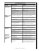
Electrode Setting: Wayne
1/16"
5/16"
Nozzle
5/32" Gap
Electrode
Top View Side View
Gap
1/8"
1/8"
3/8"
1/2"
3/16"
Top View Side View
Nozzle
Adapter
2-7/8"
Periodically Check Wiring Connections. If Necessary
To Adjust Electrodes, Use Diagram.
Electrodes
Electrode Setting: Beckett