
Specifications


10
STP SERIES PRESSURE WASHER OPERATOR’S MANUAL
Shark STP • 8.914-341.0 / 97-6153 • REV. 6/07
and block air flow which will affect burner combustion.
When soot has been detected on visual observation, the
soot on the coil must be washed off after coil has been
removed using the following steps:
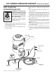
1. Remove the tank head assembly by lifting the tank
head off.
2. Remove the two pipe nipples and associated fit-
tings.
3. Lift the coil out of the outer wrap.
CAUTION: the coil weighs about 80 lbs. Use proper
lifting techniques.
4. Clean, repair and replace the coil by reversing the
above steps.
Coil Reinstallation
Reinstall by reversing the above steps 4 through 1.
Rupture Disk
If pressure from pump or thermal expansion should
exceed safe limits, the rupture disk will burst, allowing
high pressure to be discharged through hose to ground.
When the disk ruptures, it will need to be replaced.
Fuel:
Use clean fuel oil that is not contaminated with water
and debris. Replace fuel filter and drain tank every 100
hours of operation. Use Kerosene No. 1 or No. 2 Heating
Fuel (ASTM D306) or diesel only. NEVER use gasoline
in your burner tank. Gasoline is more combustible than
fuel oil and could result in a serious explosion. NEVER
use crankcase or waste oil in your burner. Fuel unit
malfunction could result from contamination.
Ignition Circuit:
Periodically inspect wires, spring contact and elec-
trodes for condition, security and proper spacing. For
transformer test (CAUTION 10,000 VOLTS) use defect
free insulated screwdriver and keep fingers off blade!
Lay blade across one contact: OK if arc will span 1/2"
between end of blade and other contact (see following
illustration).
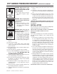
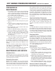
Electrode Setting: Beckett
Burner Nozzle:
Keep the tip free of surface deposits by wiping it with a
clean, solvent-saturated cloth, being careful not to plug
or enlarge the nozzle. For maximum efficiency, replace
the nozzle each season.
Fuel Control System:
The STP utilizes a fuel solenoid valve located on the fuel
pump to control flow of fuel to the combustion chamber.
This solenoid is activated by a pressure switch located
on the unloader valve. When an operator releases the
trigger on the spray gun, the pressure drops, allowing
the pressure switch to activate the fuel solenoid. The
solenoid then closes, shutting off the supply of fuel to the
combustion chamber. Controlling the flow of fuel in this
way gives an instantaneous burn or no burn situation,
thereby eliminating high and low water temperatures, and
combustion smoke normally associated with machines
incorporating a spray gun. Periodic inspection is recom-
mended to insure that the fuel solenoid valve functions
properly. This can be done by operating the machine and
checking to see that when the trigger on the spray gun is
in the off position, the burner is not firing.
Fuel Pressure Adjustment:
To adjust fuel pressure, turn the adjusting screw with a
screwdriver (located on the fuel pump) clockwise to
increase, counterclockwise to decrease. Do not exceed
200 PSI.
Air Adjustment
Machines are preset and performance tested at the
factory — elevation 100' above sea level. A one time
correction for your location will pay off in economy,
performance and extended service life. If a smoky or
eye-burning exhaust is being emitted from the stack,
two things should be checked.
First, check the fuel to be certain that kerosene or No.
1 home heating fuel is being used.
Next, check the air adjustment on the burner. An oily,
black, smoky fire indicates a lack of air and the air band
should be moved to allow the air to flow through the
burner. Sharp, eye-burning fumes indicate too much
air flowing through the combustion chamber. The air
band should be moved to allow less air to flow through
the burner.
To adjust: Start the machine and turn burner ON.
Loosen two locking screws found in the air shutter
openings (refer to illustration) and close air shutter until
black smoke appears from burner exhaust vent. Note
air band position. Next slowly open the air shutter until
white smoke just starts to appear. Turn air shutter half-
way back to the black smoke position previously noted.
Tighten locking screws.
Side View
Top View
Nozzle
1/16"
7/16"
Electrode
5/32" Gap