MIDI ATX PC CASE Handbuch Manual Manuel d‘utilisation Guia usario Manuale d´istruzioni Gebruiksaanwijzing Guia usário Instukcja obstugi !! FURIOUS
Content 20 2. Package content 20 3. The case at a glance 21 4. Installation of a mainboard 23 5. Installation of a PSU 26 6. Installation of a HDD 26 7. Installation of an optical device 27 8. Installation of a 3.5" device 29 9. Installation of an add-on card 30 FURIOUS ENGLISH 1.
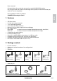
Dear customer! Congratulations for purchasing one premium quality SHARKOON product. For a long life time and to take full advantage of this product we recommend that you read this manual completely. Have a good time with our product! SHARKOON Technologies GmbH ENGLISH 1. Features • • • • • • • • • • • • ATX form factor 5x 5.25" drive bays (external) 1x 3.5" drive bay (external) 4x 3.
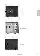
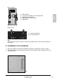
B B C C A ENGLISH D A Speaker (A), cable manager (B), cable adapter (preinstalled/C), keys (D) Mounting rails for drives (3.5" (A) and 5.25" (B)) and HDDs (C) Note: If you are missing any of the items listed above, please contact customer service via e-mail at support@sharkoon.com or call: + 49 (0) 6403 – 775 6100 3. The case at a glance Front view (closed) A B C A– B– C– D– 5.25" drive bays Front connectors, power and reset button 3.
Side view (closed/left) A A – Vent B – Lock ENGLISH B Side view (opened/left) A B A – Drive bays for 5.
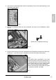
Back side view A D A– B– C– D– E– PSU bracket 1 fan pre-installed in the case’s back side Opening for I/O shield Openings for water cooling Slot bezels ENGLISH B C E Bottom view A A – Case feet (fold-out) B – Case feet (fold-in) B Note: For more information on how to install the intended devices, refer to their respective documents. 4. Installation of a mainboard 1. Open the case by removing the left panel and place it sidewise on a even surface. 2.
The mainboard contains special screw openings (fig. 2). ENGLISH fig. 2 Place the mainboard to the mounting panel. A stand-off must be screwed into every drilling of the mounting panel visible through the mainboard’s screw openings. 3. Remove the mainboard and screw the stand-offs into the respective drillings of the mounting panel (fig. 3 and 4). (Stand-offs) fig. 3 fig.
4. Press the I/O shield (delivered with the mainboard) into the I/O shield opening in the case’s back side (fig. 5). ENGLISH fig. 5 5. Place the mainboard back onto the stand-offs and screw the mainboard to them (fig. 6). (Screws for mainboard mounting) fig. 6 6. Plug the connectors of the case’s front bezel to the respective connectors of the mainboard (fig. 7 / also refer to your mainboard’s manual for further information).
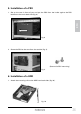
5. Installation of a PSU 1. Set up the case in front of you and put the PSU from the inside against the PSU bracket on the case’s back side (fig. 8). ENGLISH fig. 8 2. Screw the PSU to the case from the outside (fig. 9). (Screws for PSU mounting) fig. 9 6. Installation of a HDD 1. Attach the mounting rails to the HDD from both sides (fig. 10). fig.
2. Slide the HDD with attached mounting rails into the case’s HDD cage until they lock (fig. 11). ENGLISH fig. 11 3. Connect the HDD to the power supply and the mainboard. Note: A maximum of four 3.5" HDDs may be installed into the HDD cage. More HDDs may be installed to the mounting bays for 5.25" drives at the case’s front using e.g. the SHARKOON Vibe-Fixer mounting frames. 7. Installation of an optical device 1. Open the case’s front bezel. 2. Remove the 5.
3. Attach the mounting rails to the optical device from both sides (fig. 13). ENGLISH fig. 13 4. Slide the optical device with attached mounting rails into the case’s drive bay until they lock (fig. 14). fig. 14 5. Connect the optical drive to the power supply and the mainboard and close the case’s front bezel. Note: If you intend to transport the case we recommend to additionally secure the installed drive by using screws. (Screws for 5.
8. Installation of a 3.5" device 1. Open the case’s front bezel. 2. Remove the 3.5" front bezel of the 3.5" mounting bay by loosening its screws and pushing the bezel to the inside (fig. 15). ENGLISH fig. 15 3. Carefully take out the metal bezel that closes the 3.5" drive bay by using a gripper (fig. 16). fig. 16 4. Attach the mounting rails to the 3.5" device from both sides (fig. 17). fig.
5. Slide the 3.5" device with attached mounting rails into the case’s drive bay until they lock (fig. 18). ENGLISH fig. 18 6. Connect the 3.5" device to the power supply and the mainboard and close the case’s front bezel. Note: In case the installed device is not flush with the front bezel, you can adjust the mounting rail’s retaining pins. 9. Installation of an add-on card 1. Unlock the fixation clip (pull upwards), take it away and remove the slot bezel (fig. 19 and 20). fig. 19 fig.
2. Insert the add-on card into the mainboard’s respective slot and fix it to the case by re-attaching and locking the fixation clip (fig. 21 and 22). ENGLISH fig. 21 fig. 22 Note: Alternatively you may also screw the add-on card to the case (therefore use the screws for PSU mounting / fig. 23). (Screws for PSU mounting) fig.
Legal disclaimer For potential damages, especially due to inappropriate handling, SHARKOON assumes no liability. All named products and descriptions are trademarks and/or registered trademarks of the respective manufacturers and are accepted as protected. ENGLISH As a continuing policy of product improvement at SHARKOON, the design and specifications are subject to change without prior notice. National product specifications may vary.