Handbuch Manual Manuel d‘utilisation Guia usario 使用手冊 Manuale d´istruzioni Gebruiksaanwijzing Guia usário Instukcja obstugi
Content 1. Features 2. Specifications 2.1 Overview 2.2 Temperature range and humidity 2.3 Mains voltage and protective functions 2.4 Safety standards 3. Parts and accessory 4. The modular system of the Rush Power 4.1 The connectors at the PSU 4.2 The modular cables 5. Installation 5.1 Installing the Rush Power into a PC case 5.2 Connecting the PC components to the PSU 5.2.1 The connectors at a glance 5.2.2 Connecting mainboard and graphics card(s) 5.2.
Dear customer! Congratulations for purchasing one premium quality SHARKOON product. For a long life time and to take full advantage of this product we recommend that you read this manual completely. Have a good time with our product! SHARKOON Technologies GmbH 1. Features ATX 12 V v.2.31: Supports the latest Intel and AMD processor based systems. Separate 12 V rails: Separate 12 V rails guarantee a stable power supply for all components.
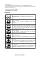
WARNING To prevent the risk of electric shock, do not open the power supply housing. No user-exchangeable parts inside. For service and maintenance refer to authorized SHARKOON personnel. Warranty is void under unauthorized attempt to open the power supply housing. Suitable for indoor or office use only. Keep the power supply away from humidity! 2. Specifications 2.1 Overview Model No. Input (AC) Output (DC) Max. Output Current Max.
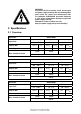
2.2 Temperature range and humidity Operation 0 to +40 °C 20 – 85% rel. humidity, non-condensing Storage -40 to +70 °C 5 – 90% rel. humidity, non-condensing 2.3 Line voltage and protective functions This PSU works with 100 to 240 V (50/60 Hz) and is equipped with the following protective functions: 1. Over voltage protection: The power supply provides a latch mode against over voltage, as defined below: Min. Max. Unit +5 V 5.74 7.5 Volt +3.3 V 3.76 4.8 Volt +12 V 13.
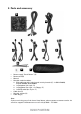
3.
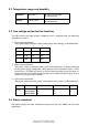
4. The modular system of the Rush Power The special feature of this PSU is the so called cable management system to connect the peripheral devices. Thanks to this modular system only the really required cables need to be connected thus keeping your case proper and optimizing the airflow within. 4.1 The connectors at the PSU A B C A B C – – – 1x 10-pin connector for SATA cables 4x 4-pin connector for 4-pin cables 2x 6-pin connector for PCIe cables 4.
1x connector cable for peripheral devices (4-pin PSU connector) for optical drives (2 connectors) and floppy (1 connector). 1x connector cable for peripheral devices (4-pin PSU connector) for optical drives (3 connectors). 1x SATA connector cable (10-pin PSU connector) for SATA drives (6 connectors). 5. Installation Remove an already installed PSU from the case. Proceed as follows: 1. Switch off your PC. Disconnect the PSU’s power cord from the wall outlet and your PSU.
5.2 Connecting the PC components to the PSU 5.2.
Note: All connectors are designed fault-preventing to avoid misconnection. If you cannot attach the female connector to the drive’s or peripheral’s male connector, please check if both connectors are attached in the correct orientation. Do not force to plug the female connector into the male connector in wrong orientation, nor modify any of the components, as this will damage the PSU and your hardware. SHARKOON warranty does not cover damage caused by incorrect handling. 5.2.
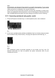
3. In case your PCIe graphics card is equipped with an additional power connector, also plug the 6-pin (fig. 3a) or 6+2-pin (fig. 3b) PCIe power connector which will provide a stable power support for your graphics card. fig. 3a fig. 3b 5.2.3 Connecting optical drives and other peripheral devices 1. Connect the 4-pin plug (fig. 4), the SATA plug (fig. 5) and the 4-pin floppy plug (fig. 6) to the respective peripheral devices. fig. 4 fig. 5 fig.
6. Troubleshooting In case the power supply does not work properly, check the following topics: 1. 2. 3. 4. Is the power cord correctly connected to a wall outlet and the PSU’s power connector? Make sure the on/off switch is turned to the “I” position. Check if the main power connector is correctly plugged to the mainboard. Check if the power connectors are properly connected to the peripheral devices in case the short circuit protection function was activated when switching on the PSU. 5.
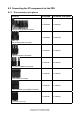
4PIN RED BLACK BLACK +5V GND GND YELLOW +12V1 RED BLACK BLACK +5V GND GND YELLOW +12V1 RED BLACK BLACK +5V GND GND YELLOW +12V1 YELLOW BLACK BLACK RED +12V1 GND GND +5V RED BLACK BLACK +5V GND GND 4PIN 4-pin power connector for peripherals YELLOW +12V1 RED BLACK BLACK +5V GND GND YELLOW 4-pin power connector for peripherals + 4-pin power connector for floppy RUSH POWER M +12V1
YELLOW +12V1 GND +5V GND +3.3V YELLOW +12V1 GND +5V GND +3.3V YELLOW +12V1 GND +5V GND +3.3V YELLOW +12V1 GND +5V GND +3.3V YELLOW +12V1 GND +5V GND +3.3V YELLOW +12V1 GND +5V GND +3.