3VT-N100 13VT-N150 13VT-CN10 SERVICE MANUAL SY9U113VTN100 TV/VCR COMBINATION Chassis No. B99B MODELS 13VT-N100 13VT-N150 13VT-CN10 In the interests of user-safety (Required by safety regulations in some countries ) the set should be restored to its original condition and only parts identical to those specified should be used. CONTENTS » » » » » » » » » » » » » » » » » » Page IMPORTANT SERVICE SAFETY PRECAUTION ............................................................................
13VT-N100 13VT-N150 13VT-CN10 IMPORTANT SERVICE SAFETY PRECAUTION Ë Service work should be performed only by qualified service technicians who are thoroughly familiar with all safety checks and servicing guidelines which follow: WARNING X-RADIATION AND HIGH VOLTAGE LIMITS 1. For continued safety, no modification of any circuit should be attempted. 2. Disconnect AC power before servicing. 3. Semiconductor heat sinks are potential shock hazards when the chassis is operating. 4.
13VT-N100 13VT-N150 13VT-CN10 IMPORTANT SERVICE SAFETY PRECAUTION (Continued) » Connect the resistor connection to all exposed metal parts having a return to the chassis (antenna, metal cabinet, screw heads, knobs and control shafts, escutcheon and etc.) and measure the AC voltage drop across the resistor. AII check must be repeated with the AC line cord plug connection reversed. (If necessary, a nonpolarized adapter plug must be used only for the purpose of completing these check.
13VT-N100 13VT-N150 13VT-CN10 PRECAUTIONS A PRENDRE LORS DE LA REPARATION Ë Ne peut effectuer la réparation qu' un technicien spécialisé qui s'est parfaitement accoutumé à toute vérification de sécurité et aux conseils suivants. LIMITES DES RADIATIONS X ET DE LA HAUTE TENSION AVERTISSEMENT 1. N'entreprendre aucune modification de tout circuit. C'est dangereux. 2. Débrancher le récepteur avant toute réparation. 3.
13VT-N100 13VT-N150 13VT-CN10 PRECAUTIONS A PRENDRE LORS DE LA REPARATION (Suite) » Toucher avec la sonde d'essai les pièces métalliques exposées qui présentent une voie de retour au châssis (antenne, coffret métallique, tête des vis, arbres de commande et des boutons, écusson, etc.) et mesurer la chute de tension CA en-travers de la résistance. Toutes les vérifications doivent être refaites après avoir inversé la fiche du cordon d'alimentation.
13VT-N100 13VT-N150 13VT-CN10 ELECTRICAL SPECIFICATIONS TV SECTION POWER INPUT: POWER RATING: PICTURE SIZE Width: Height: Depth: CONVERGENCE: SWEEP DEFLECTION: FOCUS: INTERMEDIATE FREQUENCIES Picture IF Carrier Frequency: Sound IF Carrier Frequency: Color Sub-Carrier Frequency: AUDIO POWER OUTPUT RATING: SPEAKER Size: Voice Coil Impedance: VHF/UHF ANTENNA INPUT IMPEDANCE: TUNING RANGES VHF-Channels: UHF -Channels: CATV Channels: 120 V AC 60 Hz 65 W 37.8 cm 38.7 cm 38.
13VT-N100 13VT-N150 13VT-CN10 LOCATION OF USER'S CONTROL Description Of Controls FRONT TV • VCR COMBINATION POWER POWER/ WAKE-UP TIMER REC PROGRAM TAMPER TIMER PROOF POWER button SENSOR AREA FOR REMOTE CONTROL POWER/ WAKE-UP TIMER REC VIDEO/AUDIO Input Jacks PROGRAM TAMPER TIMER PROOF TAMPER PROOF indicator PROGRAM TIMER indicator REC indicator VOLUME UP/DOWN buttons CHANNEL UP/DOWN buttons EZ REC PLAY button button PLAY button REW (Reverse Video Search) button POWER indicator STOP/EJECT
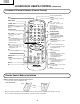
13VT-N100 13VT-N150 13VT-CN10 LOCATION OF USER'S CONTROL (Continued) Location Of Control’s Buttons (Remote Control) Infrared Transmitter Window INPUT TV/VIDEO Select DISPLAY • Used to change the On Screen Display. POWER ON/OFF CHANNEL SELECT INPUT DISPLAY 1 2 3 4 •5 6 FLASHBACK Returns to previously viewed channel. COUNTER RESET • Used to reset the tape counter. TAPE SPEED • Used to select the recording tape speed. PLAY • Used for tape playback.
13VT-N100 13VT-N150 13VT-CN10 DISASSEMBLY AND REASSEMBLY 1. 2. 3. 4. Remove the 7 rear cover fixing screws and detach the rear cover. Take out the anode cap, CRT PWB, connectors K and M, coating earth, Speaker chip fixing screws and others. Take out the main PWB unit and the VCR unit. Remove the 5 VCR fixing screws, and detach the shielding case.
13VT-N100 13VT-N150 13VT-CN10 DISASSEMBLY AND REASSEMBLY (Continued) 5. 6. 7. 8. 9. Remove the 4 cassette housing control fixing screws, and detach the cassette housing control. Remove the 2 mechanism chassis angle fixing screws, and remove the 1 head amp shielding case fixing screw. Remove the 3 mechanism chassis fixing screws, and detach the mechanism chassis from the main PWB. Remove the 2 main PWB fixing screws, and detach the main PWB.
13VT-N100 13VT-N150 13VT-CN10 DISASSEMBLY AND REASSEMBLY (Continued) For servicing any of the components inside, disconnect the lead dressing holder. Position the main PWB unit upright as shown below and connect the leads for starting the services.
13VT-N100 13VT-N150 13VT-CN10 INSTALLATION AND SERVICE INSTRUCTIONS Note: (1) When performing any adjustments to resistor controls and transformers use non-metallic screwdriver or TV alignment tools. (2) Before performing adjustment, TV set must be on at least 15 minutes. CIRCUIT PROTECTION HIGH VOLTAGE CHECK The receiver is protected by a 4.0A fuse (F701), mounted on PWB-A, wired into one side of the AC line input.
VT-N100 13VT-N150 13VT-CN10 The N-series SHARP TV/VCR COMBINATION have most of the analog setup adjustments eliminated. Coil and variable resistor adjustments are now performed digitally by using the remote controller or set’s volume and channel change function buttons. Note: There are still a few analog adjustments in the L-series such as 120V adjust, focus, master screen voltage and coils in the picture I/F detector circuit. Follow the steps below, whenever service adjustment is required.
13VT-N100 13VT-N150 13VT-CN10 Table - A ADJUSTMENT ITEM PICTURE TINT COLOR BRIGHT SHARP PHASE H-PHASE RF-AGC V-AMP PIF-VCO R CUT-OFF G CUT -OFF B CUT-OFF G GAIN B GAIN MUTE DATA INTIAL VALUE RANGE 16 0~63 39 0~77 13 0~63 32 0~63 7 0~13 0 0~7 20 0~31 18 0~63 32 0~63 40 0~127 0 0~255 0 0~255 0 0~255 128 0~255 128 0~255 0 0~2 ENERGY SAVE BALANCE TEXT BOX TEXT PICTURE CCD LEVEL OPTION 45 32 15 20 7 39 0~45 0~63 0~127 0~80 0~10 0~63 ADJUSTMENT COMMENTS "0"= Normal raster, "1"= no"Y", "2"= No Vertical 13V
13VT-N100 13VT-N150 13VT-CN10 Ë SERVICE ADJUSTMENT VCO Adjustment White Balance Adjustment 1. Connect a digital voltmeter between pin (44) of IC401 and ground. 2. Select a good local channel. 3. Enter the service mode and select the service adjustment item "PIF-VCO" and set the data value to "40". 4. Adjust the VCO coil L202 so that the digital voltmeter reads 2.5V. 5. Adjustment is complete, remove the voltmeter and return to "normal" mode. 1. Select a good local channel. 2.
13VT-N100 13VT-N150 13VT-CN10 Vertical-Size Adjustment 1. Select a good local channel. 2. Enter the service mode and select the service adjustment item "V-AMP". 3. While observing the top and bottom of the screen, adjust "V-AMP" data value to proper vertical size and linearity. Horizontal Position Adjustment 1. Select a good local channel. 2. Enter the service mode and select the service adjustment item "H-PHASE". 3. Adjust "H-PHASE" data value so that picture is centered.
13VT-N100 13VT-N150 13VT-CN10 PRECAUTIONS IN REASSEMBLING MOUTING THE CASSETTE CONTROLLER Initial setting is indispensable before placing the cassette controller in the mechanism. The initial setting is made in two ways;electrical and mechanical. Electrical setting: Make a short-circuit between TP7701 and TP7702 and be sure that the mechanism is back to its initial setting position (*1). Now place the cassette controller in position.(This method is used when the mechanism has been already set on its PWB.
13VT-N100 13VT-N150 13VT-CN10 FUNCTION OF MAJOR MECHANICAL PARTS (TOP VIEW) Drum Ass'y 17 21 Take-up Pole Base Ass'y 20 Automatic Head Cleaner Ass'y Drum Motor 19 11 A/C Head Ass'y 22 Fixing Guide 16 Full Erase 1 Head Pinch Roller Lever Ass'y 10 Pinch Drive Cam Supply Pole Base Ass'y 2 13 Reverse Guide Lever Ass'y Sup Main 7 Brake Ass'y 8 Pinch Drive Lever Ass'y Tension 3 Arm Ass'y 14 Casecon Drive Gear 9 Tu Main Brake Ass'y 6 Supply Reel Disk 15 8 Idler Wheel Ass'y 18 Loading Motor Ta
13VT-N100 13VT-N150 13VT-CN10 FUNCTION OF MAJOR MECHANICAL PARTS (BOTTOM VIEW) Capstan D. D. Motor 3 Drive Belt 4 Slow Brake 1 8 Shifter Master Cam 2 Casecon Drive Gear 7 5 Clutch Lever 6 Limiter Pulley Ass'y No. Function No. Function 1. Slow brake Gets in contact with the capstan D.D. motor linking to the master cam in the slow still mode, and brakes it to a certain degree. 6. Limiter pulley ass’y Transmits the power of the capstan D.D. motor to the reel disk via the drive idler. 8. 3.
13VT-N100 13VT-N150 13VT-CN10 ADJUSTMENT, REPLACEMENT AND ASSEMBLY OF MECHANICAL UNITS The explanation given below relates to the on-site general service (field service) but it does not relates to the adjustment and replacement which need high-grade equipment, jigs and skill. For example, the drum assembling, replacement and adjustment service must be performed by the person who have finished the technical courses.
13VT-N100 13VT-N150 13VT-CN10 No. Jig ltem Part No. Code Configuration Remarks These tapes are especially used for electrical fine adjustment. Video 10. Alignment Tape Guide roller height 11. adjustment drive Audio Hi-Fi Audio Track 525 Monoscope 7k — 58µm NTSC Color Bar 1k — 58µm 525 Monoscope 7k — 525 Monoscope 1k — 46/58 µm 19µm VROATSV CD VRONBZGS VROEBZCS CB JiGDRiVERH-4 AP This screwdriver is used for adjusting the guide roller height. 12.
13VT-N100 13VT-N150 13VT-CN10 MAINTENANCE CHECK ITEMS AND EXECUTION TIME Perform the maintenance with the regular intervals as follows so as to maintain the quality of machine. Parts Maintained 500 1000 1500 2000 3000 hrs. hrs. hrs. hrs. hrs. Possible symptom encountered Remarks Abnormal rotation or significant vibration requires replacement. Guide roller ass’y Sup Guide Shaft Lateral noises Head occasionally blocked Retaining guide Clean tape contact part with the specified cleaning liquid.
13VT-N100 13VT-N150 13VT-CN10 REMOVING AND INSTALLING THE CASSETTE HOUSING • Removal 1. In the cassette eject mode, remove the cassette. 2. Unplug the power cord. 3. Remove in the following numerical order. a) Remove two screws 1. b) Slide and pull up the cassette housing control. 1 Notes: 1. When fitting the S/E sensor holder to the cassette controller frame L/R, take care. 2. Misengagement of teeth of casecon drive gear and drive angle gear causes malfunction.
13VT-N100 13VT-N150 13VT-CN10 REEL DISK REPLACEMENT AND HEIGHT CHECK • 1. 2. 3. 4. Removal Remove the cassette housing control assembly. Pull the tension band out of the tension arm ass'y. Remove the Sup/Tu main brake ass'y. Open the hook at the top of the reel disk, and remove the reel disk. Note: Take care so that the tension band ass'y and main brake ass'y (especially soft brake) are not deformed.
13VT-N100 13VT-N150 13VT-CN10 Note: Whenever replacing the reel disk, perform the height checking and adjustment. Reel disk height adjusting jig Master plane 10 ± 0.2mm Notes: 1. Hold the torque gauge by hand so that it is not moved. 2. Do not keep the reel disk in lock state. Do not allow long-time measurement. CHECKING AND ADJUSTMENT OF TAKEUP TORQUE IN REWIND MODE Mechanism chassis Reel disk • Remove the cassette housing control assembly.
13VT-N100 13VT-N150 13VT-CN10 Notes: 1. Hold the torque gauge by hand so that it is not moved. 2. Do not keep the reel disk in lock state. Do not allow long-time measurement. CHECKING AND ADJUSTMENT OF TAKEUP TORQUE IN VIDEO SEARCH REWIND MODE • Remove the cassette housing control assembly. CHECKING AND ADJUSTMENT OF TAKEUP TORQUE IN RECORD/PLAYBACK MODE • After short-circuiting TP7701 and TP7702 provided at the left on the main PWB, plug in the power cord, then turn on the power.
13VT-N100 13VT-N150 13VT-CN10 CHECKING THE VIDEO SEARCH REWIND BACK TENSION • Remove the cassette housing control assembly. • After short-circuiting TP7701 and TP7702 provided at the left on the main PWB, plug in the power cord, then turn on the power. Tension gauge 900 - 1,200g Pinch roller • Checking 1. After pressing the play button, press the rewind button, and set the video search rewind mode. 2.
13VT-N100 13VT-N150 13VT-CN10 2. Visually check to see if the right edge of the tension pole is within the 1.5 ± 0.25mm from the right edge of the Sup guide shaft. Tension pole adjuster adjusting range Tension pole adjuster Sup guide shaft 90° Tension pole 1.5 ± 0.25mm 90° -0.1 1.6 -0.6 mm Make the adjustment with the beginning of a T-120 tape. Figure 1-18. Figure 1-15. At left side from the center line Adjust so that the delta mark of tension pole adjuster is within 90° range (left, right).
13VT-N100 13VT-N150 13VT-CN10 • Adjustment 1. If the indication of torque cassette meter is lower than the setting, shift the tension spring engagement to the part A. 2. If the indication of torque cassette meter is higher than the setting, shift the tension spring engagement to the part B. A • Checking the brake torque at the take-up side Torque gauge Tension arm B CW CCW Take-up reel disk Tension spring Figure 1-20. CCW: 8.8~23.5mN⋅m (90~240gf⋅cm) CW: 4.9~11.
13VT-N100 13VT-N150 13VT-CN10 REPLACEMENT OF A/C (Audio/Control) HEAD 1. Remove the cassette housing control assembly. 2. In unloading state, unplug the power cord. • Removal 1. Remove the screws 123, Azimuth screw and Tilt screw. 2. Unsolder the PWB fitted to the A/C head Notes: 1. When replacing, never touch the head. If you touched, clean with the cleaning liquid. 2. When removing the screw 3, take care so that the spring may spring out. 3.
13VT-N100 13VT-N150 13VT-CN10 A/C HEAD HEIGHT ROUGH ADJUSTMENT HEIGHT ADJUSTMENT OF REVERSE GUIDE • Setting 1. Adjust the height from the mechanism chassis to the reverse guide lower flange to 13.38mm, using the reverse guide height adjustment jig, in tape loading state. (Refer to Figure 1-28 (a) (b).) Azimuth screw Reverse guide Reverse guide height adjusting jig Height screw Reverse guide height adjusting jig Tilt screw Mechanism chassis Cassette tape 13.38mm (b) (a) Figure 1-28. 500g 2.
13VT-N100 13VT-N150 13VT-CN10 ADJUSTMENT OF TAPE DRIVE TRAIN 1. Tape run rough adjustment 1 Remove the cassette housing control assembly. 2 After shortcircuiting TP7701 and TP7702 provided at the main PWB, plug in the power cord, then turn on the power. 3 Check and adjust the position of the tension pole. (See page 28.) 4 Check and adjust the video search rewind back tension. (See page 27.) 5 Connect the oscilloscope to the test point for PB CHROMA envelope output (TP3301).
13VT-N100 13VT-N150 13VT-CN10 3. Tape run adjustment 1 Connect the oscilloscope to PB CHROMA envelope output test point, set oscilloscope sync to EXT, trigger-input the PB CHROMA signal (head switching pulse). 2 Rough adjustment of X value Tentatively fix A/C head arm screws 1 and 2 by the method described in Page 30 "Replacement 3". After shortcircuiting TP7701 and TP7702, plug in the powercord, then turn on the power. And playback the alignment tape (VRONBZGS).
13VT-N100 13VT-N150 13VT-CN10 REPLACEMENT OF THE CAPSTAN D.D. (DIRECT DRIVE) MOTOR • Remove the mechanism from the main PWB (refer to Page10 "DISASSEMBLY AND REASSEMBLY" Remove the cassette housing Assembly. • Removal (Follow the order of indicated numbers.) 1. Remove the reel belt 1. 2 Capstan D.D. motor control PWB Capstan D.D. motor 1 REPLACEMENT OF DRUM D.D. MOTOR 1. Set the eject mode. 2. Withdraw the main power plug from the socket. • 1. 2. 3. 4. 5. Removal (Perform in numerical order.
13VT-N100 13VT-N150 13VT-CN10 REPLACING THE UPPER AND LOWER DRUM ASSEMBLY ASSEMBLING OF PHASE MATCHING MECHANISM COMPONENTS • Assemble the phase matching mechanism components in the following order. 1. Assemble the pinch roller assembly and pinch drive cam. 2. Mounting the shifter (on the back of the mechanism chassis). 3. Mounting the master cam (on the back of the mechanism chassis). 4. Assemble the connection gear, slow brake and loading motor parts.
13VT-N100 13VT-N150 13VT-CN10 1Insert Reverse Guide Lever Ass’y Insert reverse guide lever ass'y 2 Insert pinch drive cam Align here. Turn the reverse guide lever assembly counterclockwise to the stopper. Fit the pinch drive cam so that the notch of pinch drive cam aligns with the dent of pinch drive lever assembly. Fit the pinch drive cam so that the notch of pinch drive lever assembly aligns with the half-round notch of chassis. Pinch drive lever ass'y Figure 1-41-1.
13VT-N100 13VT-N150 13VT-CN10 1. Make sure that the loading gear is at the point 1 as shown below. 2. Install, paying attention to 6 insertion points and 3 release points. 3. For the phase matching at the insertion point 1, see the point 2 as shown below. 4. Finally fix the inserts 1 and 4. INSTALLING THE SHIFTER Drum Capstan D.D. motor Reel pulley (Bottom side of mechanism chassis) Phase-Matching point 2 Figure 1-42.
13VT-N100 13VT-N150 13VT-CN10 INSTALLING THE MASTER CAM (AT REAR SIDE OF MECHANISM CHASSIS) REPLACEMENT OF LOADING MOTOR • Removal 1. Make sure beforehand that the shifter is at the point as shown below. 2. Place the master cam in the position as shown below. E-ring (XRESJ30-06000) Apply grease Apply grease Master cam Fully turn clockwise No grease Fully turn counterclockwise Face the wide tooth side ward Figure 1-44-1.
13VT-N100 13VT-N150 13VT-CN10 ASSEMBLY OF CASSETTE HOUSING 1. Drive Gear and R Drive angle ass’y MSPRT0381AJFJ Apply grease Apply grease Apply grease Figure 1-47. 2. Synchro Gear, Drive Gear L and Drive Gear R LANGF9592AJFW Top surface should be free from scratches or soil. Drive angle Drive gear R Frame Figure 1-48.
13VT-N100 13VT-N150 13VT-CN10 ADJUSTMENT OF THE VCR ELECTRICAL CIRCUITRY Notes: » Before the adjustment: Electrical adjustments described here are often required after replacement of electronic components and mechanical parts such as video heads. Check that the mechanism and all electric components are in good working condition prior to the adjustments, otherwise adjustments can not be completed.
13VT-N100 13VT-N150 13VT-CN10 Ë Test points layout of Main Unit. Figure 2-2. ADJUSTMENT OF STILL PICTURE VERTICAL SYNC Measuring instrument Monitor screen Mode EP still picture playback Input signal Self-recording tape Test point Monitor screen Control CH '/" (TR ±/ —) buttons Specification No Vertical jitter 1. Play back the EP Self-recorded tape in the still mode. 2.
NO Check IC2001. Are signals received at pin (8) of IC2001 when the key is activated? YES Is there short-circuit in the key input? YES YES NO NO NO Check key lines to input IC2001. Check IC2001 and switches for poor soldering. Check the switch contact. FLOW CHART NO.1-2 Check power circuit. Check/replace X7701 and/or IC2001. Check poor soldering. Key-in input for VCR is not received. Is the key switch in good contact? FLOW CHART NO.1-1 Check power circuit.
YES Replace the cassette cam, gear, etc. Does the loading motor run? YES YES Is the correct voltage at the loading motor terminal? Is about 11V at pin (10) of IC7701? Does the capstan motor start when the EJECT button is pressed? YES Does the take-up reel disk turn when the capstan motor is running? YES Is reel pulse at pin (80) of IC2001 when the take-up reel disk is turning? YES Is "H" level (about 1.
D-FG D-PG about 4.5Vp-p YES 0 0 4.4 4.2 Are there the drum PG and drum FG Signals at pins (3) and (5) of connector AD? NO Check the harness ADME and the drum motor unit. Are the drum PG and drum FG signal inputted to pins (90) and (89) of IC2001, respectively? NO Is the drum motor rotating? YES No head switching pulse. YES YES NO HEAD SWITCHING PULSE TROUBLESHOOTING Replace the take up/supply reel sensors D7702/D7703. Insert the cassette, and put the unit in FF or REW mode.
Check the signal line of drum PG. Check PG and FG to pins (5) and (3) of the connector ME and the drum motor. Is there the drum FG signal at pin (89) of IC2001? NO NO YES In PB mode NO Check AT 12V at pin (4) and AT 5V at pin (7) of ME connector. Check and replace the drum motor.
NO YES Does the A/C head operate normally? YES Adjust the height of the A/C head. NO NO YES Replace A/C head. Replace the FFC AA-MH. Replace IC2001. Check the capstan FG signal line between AC connector and IC2001. Check X7701, C7707 and C7706. Only PB mode inoperative.
Check between pin (25) of IC2201 and pin (14) of IC402. YES Is there a signal at pin (25) of IC2201? YES Is there a signal at pin (20) or (16) of IC2201? NO NO NO Check IC401 and parts around it. FLOW CHART NO.1-12 Replace IC2201. YES YES Are there the I2C bus data and clock at pins (8) and (7) of IC2201? NO Is the supply voltage of NO 5V feed to pins (4), (21), (48) and (63) of IC2201? Check between pins (8) and (7) of IC2201 and all the way up thrn to pins (72) and (71) of IC2001.
Check PC5V line. Is there a signal at pin (25) of IC2201? NO Check the I2C bus data and clock at pins (8) and (7) of IC2201. NO Check between pin (30) of IC3301 and all the way up to pin (57) of IC2201. Check H.SW.P. line. NO FLOW CHART NO.1-14 YES NO Replace IC2201. Is there a signal at pin (12) NO Check peripheral circuits of of IC2201? X5502. Playback is possible but 〈CHROMINANCE〉 without color. Replace IC3301. YES Is there H.SW.P.
Check PC 5V line. NO Check A-MUTE (H) Line. (IC2201 pin (72)~ IC2001 pin (29)). YES Replace IC2201. NO Is there "H" level at pin (72) of IC2201? YES Is voltage of pins (86) and (88) of IC2201 normal? NO Check between pins (8) and (7) of IC2201 and all the way thru to pins (72) and (71) of IC2001. NO NO Check circuits around the audio output circuit in IC401 and parts around the audio inputs jack (J401). FLOW CHART NO.1-15 Check between pin (85) of IC2201 and pin (1) of IC402.
YES Replace IC2201. Check AUDIO MUTE (H) line. Are azimuth and height of the A/C head properly adjusted? NO Clean A/C head. YES YES Are the FFC MH-AA and the PB AMP's peripheral parts around pins (75)~(78) of IC2201 normal? Is there "L" level at pin (70) of IC2201? FLOW CHART NO.1-17 Check line between pin (85) of IC2201 and pin (1) of IC402. NO Is there a signal at pin (85) of IC2201? YES NO NO NO NO Replace A/C head. Readjust azimuth and height. Replace defective parts.
Check D701 thru D704, L701, and R701. NO NO NO Check T701 and adjacent parts. YES YES Does pulse waveform NO exist at line between pin (1) and (2) of IC701? Is 16V DC applied to pin (4) of IC701? YES Is 170V DC applied to C705? YES YES Is 120V AC applied to line between K701 and K702? Is AC cord connected? Set not operating Check IC701 and adjacent parts. Check IC701, R717. AC cord broken. Connect AC cord. FLOW CHART NO.
YES NO Is there a signal at NO pin (37) of IC401? 52 Abnormal Check IC401. Normal Check the Tuner circuit. Check the tuner AGC. Normal Check the tuner bias. Check the IC401 and adjacent parts. YES Check IC2001. Abnormal Is there a signal at pin NO Check the Q404 (43) of IC401? and adjacent parts. Check IC401. Normal Check the PC9V line. Abnormal Check the IC401, and adjacent parts.
Check AT8V Line and C361. Check IC401 and adjacent parts. YES Check IC401 and adjacent parts as same as "NO PICTURE". Is there a signal at pin (39) of IC401? NO PLAYBACK PICTURE Check IC351 and adjacent parts. YES YES NO Does approx. 8V appear at pin (5) of IC351? YES Does waveform appear at pin (2) of IC351? YES NO Does waveform appear at pin (54) of IC401? NO SOUND NO NO Check the VCR: TROUBLESHOOTING "NO PLAYBACK".
13VT-N100 13VT-N150 13VT-CN10 CHASSIS LAYOUT H G PWB-B F E D PWB-D C B PWB-C A 1 2 3 54 4 5 PWB-A 6 7 8 9 10 11 55 12
13VT-N100 13VT-N150 13VT-CN10 BLOCK DIAGRAM OF TV SECTION H G F E D C B A 1 2 3 56 4 5 6 7 8 9 10 11 57 12
13VT-N100 13VT-N150 13VT-CN10 BLOCK DIAGRAM OF VCR SECTION Ë OVERALL BLOCK DIAGRAM H G F E D C B A 1 2 3 58 4 5 6 7 8 9 10 11 59 12
13VT-N100 13VT-N150 13VT-CN10 BLOCK DIAGRAM OF VCR SECTION Ë SERVO PROCESS BLOCK DIAGRAM H G F E D C B A 1 2 3 60 4 5 6 7 8 9 10 11 61 12
13VT-N100 13VT-N150 13VT-CN10 BLOCK DIAGRAM OF VCR SECTION Ë SYSTEM CONTROL BLOCK DIAGRAM Ë SAFETY DEVICE BLOCK DIAGRAM H G F E D C B A 1 2 3 62 4 5 6 7 8 9 10 11 63 12
13VT-N100 13VT-N150 13VT-CN10 BLOCK DIAGRAM OF VCR SECTION Ë VIDEO SIGNAL FLOW BLOCK DIAGRAM H G F E D C B A 1 2 3 64 4 5 6 7 8 9 10 11 65 12
13VT-N100 13VT-N150 13VT-CN10 BLOCK DIAGRAM OF VCR SECTION Ë AUDIO BLOCK DIAGRAM H G F E D C B A 1 2 3 66 4 5 6 7 8 9 10 11 67 12
13VT-N100 13VT-N150 13VT-CN10 OVERALL SCHEMATIC DIAGRAM H G F E D C B A 1 2 3 68 4 5 6 7 8 9 10 11 69 12
13VT-N100 13VT-N150 13VT-CN10 SCHEMATIC DIAGRAM : CRT Unit DESCRIPTION OF SECTION SCHEMATIC DIAGRAM NOTES: H 1. The unit of resistance "ohm" is omitted (K=1000 ohms, M =1 Meg ohm). 2. All resistors are 1/8 watt, unless otherwise noted. 3. All capacitors are 50V, unless otherwise noted. 4. All capacitors are µF, unless otherwise noted. (P: µµF) 5. (G) indicates ±2% tolerance may be used. G VOLTAGE MEASUREMENT CONDITIONS: 1.
13VT-N100 13VT-N150 13VT-CN10 SCHEMATIC DIAGRAM : MAIN-1 Unit (TV Section) H G F E D C B A 1 2 3 72 4 5 6 7 8 9 10 11 73 12
13VT-N100 13VT-N150 13VT-CN10 SCHEMATIC DIAGRAM : MAIN-2 Unit (TV Section) H G F E D C B A 1 2 3 74 4 5 6 7 8 9 10 11 75 12
13VT-N100 13VT-N150 13VT-CN10 SCHEMATIC DIAGRAM : FRONT AV and POWER Unit (TV Section) H G F E D C B A 1 2 3 76 4 5 6 7 8 9 10 11 77 12
13VT-N100 13VT-N150 13VT-CN10 SCHEMATIC DIAGRAM : MAIN-3 Unit (VCR Section) H G F E D C B A 1 2 3 78 4 5 6 7 8 9 10 11 79 12
13VT-N100 13VT-N150 13VT-CN10 SCHEMATIC DIAGRAM : MAIN-4 Unit (VCR Section) H G F E D C B A 1 2 3 80 4 5 6 7 8 9 10 11 81 12
13VT-N100 13VT-N150 13VT-CN10 PRINTED WIRING BOARD ASSEMBLIES H G F E PWB-B: CRT Unit (Wiring Side) D C B PWB-D: FRONT AV Unit (Wiring Side) A 1 2 3 4 82 5 6
13VT-N100 13VT-N150 13VT-CN10 H G F E D C B A PWB-C: POWER Unit (Wiring Side) 1 2 3 4 83 5 6
13VT-N100 13VT-N150 13VT-CN10 H G F E D C B A PWB-A: MAIN Unit (Wiring Side) 1 2 3 4 84 5 6
13VT-N100 13VT-N150 13VT-CN10 H G F E D C B A PWB-A: MAIN Unit (Chip Parts Side) 1 2 3 4 85 5 6
13VT-N100 13VT-N150 13VT-CN10 Ref. No. Part No. ★ Description PARTS LIST Code Ref. No. Part No. ★ Description LISTE DES PIECES Code PARTS REPLACEMENT CHANGE DES PIECES Replacement parts which have these special safety characteristics identified in this manual ; electrical components having such features are identified by å and shaded areas in the Replacement Parts Lists and Schematic Diagrams.
13VT-N100 13VT-N150 13VT-CN10 Ref. No. ★ Part No. Description Code Ref. No. D402 D451 D455 D501 å D502 çå D651 çå D652 çå D653 D656 D670 å D710 D2001 D2003 D2007 D2008 D2010 D2201 D2202 D7701 D7702 D7703 D7704 D7705 D7712 D8301 D8302 D8303 D8304 å VA701 PWB-A: DUNTKA037FMV0 MAIN Unit TUNER NOTE: THE PARTS HERES SHOWN ARE SUPPLIED AS AN ASSEMBLY NOT INDEPENEDENTLY.
13VT-N100 13VT-N150 13VT-CN10 Ref. No. ★ Part No. Description Code Ref. No.
13VT-N100 13VT-N150 13VT-CN10 Ref. No. Part No. ★ Description Code Ref. No.
13VT-N100 13VT-N150 13VT-CN10 Ref. No. Part No. ★ Description Code Ref. No.
13VT-N100 13VT-N150 13VT-CN10 Ref. No. Part No. ★ Description Code Ref. No.
13VT-N100 13VT-N150 13VT-CN10 Ref. No. ★ Part No. Description Code Ref. No. S2001 S2501 S2502 S2503 S2504 S2505 S2506 S2507 S2508 S2509 QSW-P0593CEZZ QSW-K0077GEZZ QSW-K0077GEZZ QSW-K0077GEZZ QSW-K0077GEZZ QSW-K0077GEZZ QSW-K0077GEZZ QSW-K0077GEZZ QSW-K0077GEZZ QSW-K0077GEZZ J J J J J J J J J J J J J J J J J J J J J J J J J J J J J J J J J J J J J J J J J J J J J J J J J J J J J J J J J J J J 1k 5.6k 5.6k 100 100 1k 47k 220k 4.7k 39k 15k 18k 1k 100k 1k 1k 1k 1k 1k 1k 4.7k 680 3.
13VT-N100 13VT-N150 13VT-CN10 Ref. No. ★ Part No. Description Code Ref. No. ★ Part No.
13VT-N100 13VT-N150 13VT-CN10 Ref. No. ★ Part No. Description Code Ref. No. PWB-C: DUNTKA038WEV0 å å COILS L726 L727 RCiLP0195CEZZ or RCiLP0238CEZZ or RCiLP0285CEZZ RCiLP0179CEZZ or RCiLP0236CEZZ or RCiLP0283CEZZ RCiLP0179CEZZ J Coil 68µH AD J Coil 47µH AD J Coil 47µH AD T701 RTRNZ0161PEZZ R Transformer or RTRNZ0114PEZZ å R738 RVR-M4333CEZZ J 6.
13VT-N100 13VT-N150 13VT-CN10 Ref. No. Part No. ★ Description Code Ref. No.
13VT-N100 13VT-N150 13VT-CN10 Ref. No. Part No. ★ Description Code Ref. No.
13VT-N100 13VT-N150 13VT-CN10 Part No. ★ Description Code Ref. No. MECHANISM CHASSIS PARTS Ref. No. ★ Part No.
13VT-N100 13VT-N150 13VT-CN10 Ref. No. Part No. ★ Description Code Ref. No.
13VT-N100 13VT-N150 13VT-CN10 Part No. ★HOUSING Description Code Ref. No. PARTS Part No. CASSETTE CONTROL ★ Ref. No.
13VT-N100 13VT-N150 13VT-CN10 Ref. No. Part No.
1 2 1-1 1-5 1-7 3 101 1-12 1-16 1-17 16 1-15 30 24 20 26 20 31 22 22 33 25 41 24 44 E 1-8 1-9 22 22 9 8 7 24 26 35 36 6 34 25 4 13 28 39 24 38 19 PWB-A 23 11 40 3 28 25 42 43 15 PWB-C 26 27 Ref. No. Part No. ★ Description Code Ref. No. Part No.
13VT-N100 13VT-N150 13VT-CN10 Ref. No. Part No. ★ Description Code R TCAUH0011PEZZ R TiNS-6763PEZZ R TiNS-7005PEZZ R RRMCG1330PESA R RRMCG1330PESB R Guarantee Card (13VT-N100/150) Caution Card (13VT-N100/150) Operation Manual (13VT-N100/150) Operation Manual (13VT-CN10) Infrared R/C Unit (13VT-N100/CN10) Infrared R/C Unit (13VT-N150) Part No. ★ Description Code PACKING PARTS SUPPLIED ACCESORIES TGAN-0018PEZZ Ref. No.
13VT-N100 13VT-N150 13VT-CN10 Ref. No. Part No. ★ Description Code Ref. No. Part No. PACKING OF THE SET ★ Description • SETTING POSITIONS OF THE KNOBS Power SW OFF ★ Polyethyrene Bag Operation Manual Guarantee Card ★ Batteries Infrared R/C Unit ★ Polyethylene Sack ★ Buffer Material (Top and Bottom) ★ Packing Case ★ Serial Number Label FRONT Use 22 staples to fix the packing case. REAR ★ Number Card MARK ★ : Not Replacement Items.
13VT-N100 13VT-N150 13VT-CN10 Ref. No. Part No. ★ Description Code Ref. No. ★ Part No. Description Code COPYRIGHT © 2000 BY SHARP CORPORATION ALL RIGHTS RESERVED. No part of this publication may be reproduced, stored in a retrieval system, or transmitted in any form or by any means, electronic, mechanical, photocopying, recording, or otherwise, without prior written permission of the publisher.