
Service manual

36
13VT-N100
13VT-N150
13VT-CN10
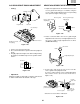
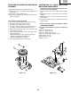
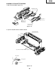
1Insert Reverse Guide Lever Ass’y
Figure 1-41-1.
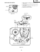
Phase Matching Point 2
Pinch Roller Double
Action Lever Ass'y
Open lever
Insert reverse guide lever ass'y
Align here.
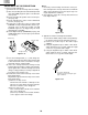
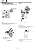
2 Insert pinch drive cam
Pinch drive lever ass'y
Fit the pinch drive cam so that the notch of pinch
drive cam aligns with the dent of pinch drive lever
assembly.
Fit the pinch drive cam so that the notch of
pinch drive lever assembly aligns with the
half-round notch of chassis.
Turn the reverse guide lever
assembly counterclockwise
to the stopper.
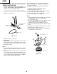
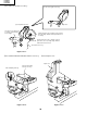
2Insert Pinch Roller/Pinch Double Action Lever Ass’y.
Figure 1-41-2.
Figure 1-41-3.
3Insert Open Lever.