3VT-R100/R150 13VT-CR10 SERVICE MANUAL S51T413VT-R10 TV/VCR COMBINATION Chassis No. B00A MODELS 13VT-R100 13VT-R150 13VT-CR10 In the interests of user-safety (Required by safety regulations in some countries ) the set should be restored to its original condition and only parts identical to those specified should be used. CONTENTS » » » » » » » » » » » » » » » » » » Page IMPORTANT SERVICE SAFETY PRECAUTION ............................................................................
13VT-R100/R150 13VT-CR10 IMPORTANT SERVICE SAFETY PRECAUTION Ë Service work should be performed only by qualified service technicians who are thoroughly familiar with all safety checks and servicing guidelines which follow: WARNING X-RADIATION AND HIGH VOLTAGE LIMITS 1. For continued safety, no modification of any circuit should be attempted. 2. Disconnect AC power before servicing. 3. Semiconductor heat sinks are potential shock hazards when the chassis is operating. 4.
13VT-R100/R150 13VT-CR10 IMPORTANT SERVICE SAFETY PRECAUTION (Continued) » Connect the resistor connection to all exposed metal parts having a return to the chassis (antenna, metal cabinet, screw heads, knobs and control shafts, escutcheon and etc.) and measure the AC voltage drop across the resistor. AII check must be repeated with the AC line cord plug connection reversed. (If necessary, a nonpolarized adapter plug must be used only for the purpose of completing these check.
13VT-R100/R150 13VT-CR10 PRECAUTIONS A PRENDRE LORS DE LA REPARATION Ë Ne peut effectuer la réparation qu' un technicien spécialisé qui s'est parfaitement accoutumé à toute vérification de sécurité et aux conseils suivants. LIMITES DES RADIATIONS X ET DE LA HAUTE TENSION AVERTISSEMENT 1. N'entreprendre aucune modification de tout circuit. C'est dangereux. 2. Débrancher le récepteur avant toute réparation. 3.
13VT-R100/R150 13VT-CR10 PRECAUTIONS A PRENDRE LORS DE LA REPARATION (Suite) » Toucher avec la sonde d'essai les pièces métalliques exposées qui présentent une voie de retour au châssis (antenne, coffret métallique, tête des vis, arbres de commande et des boutons, écusson, etc.) et mesurer la chute de tension CA en-travers de la résistance. Toutes les vérifications doivent être refaites après avoir inversé la fiche du cordon d'alimentation.
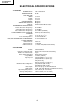
13VT-R100/R150 13VT-CR10 ELECTRICAL SPECIFICATIONS TV SECTION POWER INPUT: POWER RATING: PICTURE SIZE Width: Height: Depth: CONVERGENCE: SWEEP DEFLECTION: FOCUS: INTERMEDIATE FREQUENCIES Picture IF Carrier Frequency: Sound IF Carrier Frequency: Color Sub-Carrier Frequency: AUDIO POWER OUTPUT RATING: SPEAKER Size: Voice Coil Impedance: VHF/UHF ANTENNA INPUT IMPEDANCE: TUNING RANGES VHF-Channels: UHF -Channels: CATV Channels: 120 V AC 60 Hz 65 W 37.8 cm 38.7 cm 37.
13VT-R100/R150 13VT-CR10 LOCATION OF USER'S CONTROL Description Of Controls FRONT POWER POWER/ WAKE-UP TIMER REC PROGRAM TAMPER TIMER PROOF POWER button SENSOR AREA FOR REMOTE CONTROL POWER/ WAKE-UP TIMER REC VIDEO/AUDIO Input Jacks PROGRAM TAMPER TIMER PROOF TAMPER PROOF indicator PROGRAM TIMER indicator REC indicator VOLUME UP/DOWN buttons CHANNEL UP/DOWN buttons EZ REC PLAY button button PLAY button REW (Reverse Video Search) button POWER indicator STOP/EJECT button FF (Forward Video S
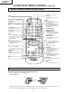
13VT-R100/R150 13VT-CR10 LOCATION OF USER'S CONTROL (Continued) Location Of Control’s Buttons (Remote Control) Infrared Transmitter Window INPUT TV/VIDEO Select DISPLAY • Used to change the On Screen Display. POWER ON/OFF CHANNEL SELECT MUTE Press → Mutes sound. Press again → Restores sound to previous level. Press the MUTE button to enter the CLOSED CAPTION mode automatically if the signal contains CC information. POWER INPUT FLASHBACK Returns to previously viewed channel.
13VT-R100/R150 13VT-CR10 DISASSEMBLY AND REASSEMBLY 1. 2. 3. 4. Remove the 7 rear cover fixing screws and detach the rear cover. Take out the anode cap, CRT PWB, connectors K and M, coating earth, Speaker chip fixing screws and others. Take out the main PWB unit and the VCR unit. Remove the 5 VCR fixing screws, and detach the shielding case.
13VT-R100/R150 13VT-CR10 DISASSEMBLY AND REASSEMBLY (Continued) 5. 6. 7. 8. 9. Remove the 4 cassette housing control fixing screws, and detach the cassette housing control. Remove the 2 mechanism chassis angle fixing screws, and remove the 1 head amp shielding case fixing screw. Remove the 3 mechanism chassis fixing screws, and detach the mechanism chassis from the main PWB. Remove the 3 main PWB fixing screws, and detach the main PWB.
13VT-R100/R150 13VT-CR10 DISASSEMBLY AND REASSEMBLY (Continued) For servicing any of the components inside, disconnect the lead dressing holder. Position the main PWB unit upright as shown below and connect the leads for starting the services.
13VT-R100/R150 13VT-CR10 INSTALLATION AND SERVICE INSTRUCTIONS Note: (1) When performing any adjustments to resistor controls and transformers use non-metallic screwdriver or TV alignment tools. (2) Before performing adjustment, TV set must be on at least 15 minutes. CIRCUIT PROTECTION HIGH VOLTAGE CHECK The receiver is protected by a 4.0A fuse (F701), mounted on PWB-A, wired into one side of the AC line input.
VT-R100/R150 13VT-CR10 The R-series SHARP TV/VCR COMBINATION have most of the analog setup adjustments eliminated. Coil and variable resistor adjustments are now performed digitally by using the remote controller or set’s volume and channel change function buttons. Note: There are still a few analog adjustments in the R-series such as 120V adjust, focus, master screen voltage and coils in the picture I/F detector circuit. Follow the steps below, whenever service adjustment is required.
13VT-R100/R150 13VT-CR10 Table - A ADJUSTMENT ITEM PICTURE TINT COLOR BRIGHT SHARP PHASE H-PHASE RF-AGC V-AMP PIF-VCO R CUT-OFF G CUT -OFF B CUT-OFF G GAIN B GAIN MUTE DATA INITIAL VALUE RANGE 16 0~63 39 0~77 13 0~63 32 0~63 7 0~13 0 0~7 20 0~31 18 0~63 32 0~63 40 0~127 0 0~255 0 0~255 0 0~255 128 0~255 128 0~255 0 0~2 ENERGY SAVE BALANCE TEXT BOX TEXT PICTURE CCD LEVEL OPTION (VCR) OPTION (TV) 45 32 15 20 10 39 31 0~45 0~63 0~127 0~80 0~24 0~63 0~255 ADJUSTMENT COMMENTS "0"= Normal raster, "1"= no"Y
13VT-R100/R150 13VT-CR10 Ë SERVICE ADJUSTMENT VCO Adjustment White Balance Adjustment 1. Connect a digital voltmeter between pin (44) of IC401 and ground. 2. Select a good local channel. 3. Enter the service mode and select the service adjustment item "PIF-VCO" and set the data value to "40". 4. Adjust the VCO coil L202 so that the digital voltmeter reads 2.5V. 5. Adjustment is complete, remove the voltmeter and return to "normal" mode. 1. Select a good local channel. 2.
13VT-R100/R150 13VT-CR10 Vertical-Size Adjustment 1. Select a good local channel. 2. Enter the service mode and select the service adjustment item "V-AMP". 3. While observing the top and bottom of the screen, adjust "V-AMP" data value to proper vertical size and linearity. Horizontal Position Adjustment 1. Select a good local channel. 2. Enter the service mode and select the service adjustment item "H-PHASE". 3. Adjust "H-PHASE" data value so that picture is centered.
13VT-R100/R150 13VT-CR10 PRECAUTIONS IN REASSEMBLING MOUTING THE CASSETTE CONTROLLER Initial setting is indispensable before placing the cassette controller in the mechanism. The initial setting is made in two ways;electrical and mechanical. Electrical setting: Make a short-circuit between TP7701 and TP7702 and be sure that the mechanism is back to its initial setting position (*1). Now place the cassette controller in position.(This method is used when the mechanism has been already set on its PWB.
13VT-R100/R150 13VT-CR10 FUNCTION OF MAJOR MECHANICAL PARTS (TOP VIEW) Drum Ass'y 17 21 Take-up Pole Base Ass'y 20 Automatic Head Cleaner Ass'y Drum Motor 19 11 A/C Head Ass'y 22 Fixing Guide 16 Full Erase 1 Head Pinch Roller Lever Ass'y 10 Pinch Drive Cam Supply Pole Base Ass'y 2 13 Reverse Guide Lever Ass'y Sup Main 7 Brake Ass'y 8 Pinch Drive Lever Ass'y Tension 3 Arm Ass'y 14 Casecon Drive Gear 9 Tu Main Brake Ass'y 6 Supply Reel Disk 15 8 Idler Wheel Ass'y 18 Loading Motor Take-up
13VT-R100/R150 13VT-CR10 FUNCTION OF MAJOR MECHANICAL PARTS (BOTTOM VIEW) Capstan D. D. Motor 3 Drive Belt 4 Slow Brake 1 8 Shifter Master Cam 2 Casecon Drive Gear 7 5 Clutch Lever 6 Limiter Pulley Ass'y No. Function No. Function 1. Slow brake Gets in contact with the capstan D.D. motor linking to the master cam in the slow still mode, and brakes it to a certain degree. 6. Limiter pulley ass’y Transmits the power of the capstan D.D. motor to the reel disk via the drive idler. 8. 3.
13VT-R100/R150 13VT-CR10 ADJUSTMENT, REPLACEMENT AND ASSEMBLY OF MECHANICAL UNITS The explanation given below relates to the on-site general service (field service) but it does not relates to the adjustment and replacement which need high-grade equipment, jigs and skill. For example, the drum assembling, replacement and adjustment service must be performed by the person who have finished the technical courses.
13VT-R100/R150 13VT-CR10 No. Jig ltem Part No. Code Configuration Remarks These tapes are especially used for electrical fine adjustment. Video 10. Alignment Tape Guide roller height 11. adjustment drive Audio Hi-Fi Audio Track 525 Monoscope 7k — 58µm NTSC Color Bar 1k — 58µm 525 Monoscope 7k — 525 Monoscope 1k — 46/58 µm 19µm VROATSV CD VRONBZGS VROEBZCS CB JiGDRiVERH-4 AP This screwdriver is used for adjusting the guide roller height. 12.
13VT-R100/R150 13VT-CR10 MAINTENANCE CHECK ITEMS AND EXECUTION TIME Perform the maintenance with the regular intervals as follows so as to maintain the quality of machine. Parts Maintained 500 1000 1500 2000 3000 hrs. hrs. hrs. hrs. hrs. Possible symptom encountered Remarks Abnormal rotation or significant vibration requires replacement. Guide roller ass’y Sup Guide Shaft Lateral noises Head occasionally blocked Retaining guide Clean tape contact part with the specified cleaning liquid.
13VT-R100/R150 13VT-CR10 REMOVING AND INSTALLING THE CASSETTE HOUSING Notes: 1. When fitting the S/E sensor holder to the cassette controller frame L/R, take care. 2. Misengagement of teeth of casecon drive gear and drive angle gear causes malfunction. (The cassette cannot be set, load and ejection are repeated). 3. In the case when you use the magnet screw driver, never approach the magnet driver to the A/C head, FE head, and drum. 4.
13VT-R100/R150 13VT-CR10 REEL DISK REPLACEMENT AND HEIGHT CHECK 4. Assemble the Sup main brake ass'y. Notes: 1. When installing the reel disk, take due care so that the tension band ass'y is not deformed and grease does no adhere. 2. Do not damage the Sup main brake ass'y. Be careful so that grease does not adhere to the brake surface. • 1. 2. 3. 4. Removal Remove the cassette housing control assembly. Pull the tension band out of the tension arm ass'y. Remove the Sup/Tu main brake ass'y.
13VT-R100/R150 13VT-CR10 Note: Whenever replacing the reel disk, perform the height checking and adjustment. Reel disk height adjusting jig Master plane 10 ± 0.2mm Notes: 1. Hold the torque gauge by hand so that it is not moved. 2. Do not keep the reel disk in lock state. Do not allow long-time measurement. CHECKING AND ADJUSTMENT OF TAKEUP TORQUE IN REWIND MODE Mechanism chassis Reel disk • Remove the cassette housing control assembly.
13VT-R100/R150 13VT-CR10 Notes: 1. Hold the torque gauge by hand so that it is not moved. 2. Do not keep the reel disk in lock state. Do not allow long-time measurement. CHECKING AND ADJUSTMENT OF TAKEUP TORQUE IN VIDEO SEARCH REWIND MODE • Remove the cassette housing control assembly. CHECKING AND ADJUSTMENT OF TAKEUP TORQUE IN RECORD/PLAYBACK MODE • After short-circuiting TP7701 and TP7702 provided at the left on the main PWB, plug in the power cord, then turn on the power.
13VT-R100/R150 13VT-CR10 CHECKING THE VIDEO SEARCH REWIND BACK TENSION • Remove the cassette housing control assembly. • After short-circuiting TP7701 and TP7702 provided at the left on the main PWB, plug in the power cord, then turn on the power. Tension gauge 900 - 1,200g Pinch roller • Checking 1. After pressing the play button, press the rewind button, and set the video search rewind mode. 2.
13VT-R100/R150 13VT-CR10 2. Visually check to see if the right edge of the tension pole is within the 1.5 ± 0.25mm from the right edge of the Sup guide shaft. Tension pole adjuster adjusting range Tension pole adjuster Sup guide shaft 90° Tension pole 1.5 ± 0.25mm 90° -0.1 1.6 -0.6 mm Make the adjustment with the beginning of a T-120 tape. Figure 1-18. Figure 1-15. At left side from the center line Adjust so that the delta mark of tension pole adjuster is within 90° range (left, right).
13VT-R100/R150 13VT-CR10 • Adjustment 1. If the indication of torque cassette meter is lower than the setting, shift the tension spring engagement to the part A. 2. If the indication of torque cassette meter is higher than the setting, shift the tension spring engagement to the part B. A • Checking the brake torque at the take-up side Torque gauge Tension arm B CW CCW Take-up reel disk Tension spring Figure 1-20. CCW: 8.8~23.5mN⋅m (90~240gf⋅cm) CW: 4.9~11.
13VT-R100/R150 13VT-CR10 3. Align the left end of gear of A/C head arm with the punched mark of chassis, tentatively tighten the screws 1 and 2 so as to ensure smooth motion of A/C head arm. Tentative tightening torque must be 0.15 to 0.20 N·m (1.5 to 2.0kgf·cm). REPLACEMENT OF A/C (Audio/Control) HEAD 1. Remove the cassette housing control assembly. 2. In unloading state, unplug the power cord. • Removal 1. Remove the screws 123, Azimuth screw and Tilt screw. 2.
13VT-R100/R150 13VT-CR10 A/C HEAD HEIGHT ROUGH ADJUSTMENT HEIGHT ADJUSTMENT OF REVERSE GUIDE • Setting 1. Adjust the height from the mechanism chassis to the reverse guide lower flange to 13.38mm, using the reverse guide height adjustment jig, in tape loading state. (Refer to Figure 1-28 (a) (b).) Azimuth screw Reverse guide Reverse guide height adjusting jig Height screw Reverse guide height adjusting jig Tilt screw Mechanism chassis Cassette tape 13.38mm (b) (a) Figure 1-28.
13VT-R100/R150 13VT-CR10 Notes: 1. Previously set the tracking control in the center position, and adjust the envelope waveform to maximum with X value adjustment nut. Thereby the tape run rough adjustment is facilitated. 2. Especially the outlet side envelope waveform must have higher flatness. ADJUSTMENT OF TAPE DRIVE TRAIN 1. Tape run rough adjustment 1 Remove the cassette housing control assembly.
13VT-R100/R150 13VT-CR10 3. Tape run adjustment 1 Connect the oscilloscope to PB CHROMA envelope output test point, set oscilloscope sync to EXT, trigger-input the PB CHROMA signal (head switching pulse). 2 Rough adjustment of X value Tentatively fix A/C head arm screws 1 and 2 by the method described in Page 30 "Replacement 3". After shortcircuiting TP7701 and TP7702, plug in the powercord, then turn on the power. And playback the alignment tape (VRONBZGS).
13VT-R100/R150 13VT-CR10 REPLACEMENT OF DRUM D.D. MOTOR REPLACEMENT OF THE CAPSTAN D.D. (DIRECT DRIVE) MOTOR 1. Set the eject mode. 2. Withdraw the main power plug from the socket. • Remove the mechanism from the main PWB (refer to Page10 "DISASSEMBLY AND REASSEMBLY" Remove the cassette housing Assembly. • 1. 2. 3. 4. 5. • Removal (Follow the order of indicated numbers.) 1. Remove the reel belt 1. Notes: 1. In removing the D.D.
13VT-R100/R150 13VT-CR10 REPLACING THE UPPER AND LOWER DRUM ASSEMBLY ASSEMBLING OF PHASE MATCHING MECHANISM COMPONENTS • Assemble the phase matching mechanism components in the following order. 1. Assemble the pinch roller assembly and pinch drive cam. 2. Mounting the shifter (on the back of the mechanism chassis). 3. Mounting the master cam (on the back of the mechanism chassis). 4. Assemble the connection gear, slow brake and loading motor parts.
13VT-R100/R150 13VT-CR10 1Insert Reverse Guide Lever Ass’y Insert reverse guide lever ass'y 2 Insert pinch drive cam Align here. Turn the reverse guide lever assembly counterclockwise to the stopper. Fit the pinch drive cam so that the notch of pinch drive cam aligns with the dent of pinch drive lever assembly. Fit the pinch drive cam so that the notch of pinch drive lever assembly aligns with the half-round notch of chassis. Pinch drive lever ass'y Figure 1-41-1.
13VT-R100/R150 13VT-CR10 1. Make sure that the loading gear is at the point 1 as shown below. 2. Install, paying attention to 6 insertion points and 3 release points. 3. For the phase matching at the insertion point 1, see the point 2 as shown below. 4. Finally fix the inserts 1 and 4. INSTALLING THE SHIFTER Drum Capstan D.D. motor Reel pulley (Bottom side of mechanism chassis) Phase-Matching point 2 Figure 1-42.
13VT-R100/R150 13VT-CR10 INSTALLING THE MASTER CAM (AT REAR SIDE OF MECHANISM CHASSIS) REPLACEMENT OF LOADING MOTOR • Removal 1. Make sure beforehand that the shifter is at the point as shown below. 2. Place the master cam in the position as shown below. E-ring (XRESJ30-06000) Apply grease Apply grease Master cam Fully turn clockwise No grease Fully turn counterclockwise Face the wide tooth side ward Figure 1-44-1.
13VT-R100/R150 13VT-CR10 ASSEMBLY OF CASSETTE HOUSING 1. Drive Gear and R Drive angle ass’y MSPRT0381AJFJ Apply grease Apply grease Apply grease Figure 1-47. 2. Synchro Gear, Drive Gear L and Drive Gear R LANGF9592AJFW Top surface should be free from scratches or soil. Drive angle Drive gear R Frame Figure 1-48.
13VT-R100/R150 13VT-CR10 ADJUSTMENT OF THE VCR ELECTRICAL CIRCUITRY Notes: » Before the adjustment: Electrical adjustments described here are often required after replacement of electronic components and mechanical parts such as video heads. Check that the mechanism and all electric components are in good working condition prior to the adjustments, otherwise adjustments can not be completed.
13VT-R100/R150 13VT-CR10 Ë Test points layout of Main Unit. Figure 2-2. ADJUSTMENT OF STILL PICTURE VERTICAL SYNC Measuring instrument Monitor screen Mode EP still picture playback Input signal Self-recording tape Test point Monitor screen Control CH '/" (TR ±/ —) buttons Specification No Vertical jitter 1. Play back the EP Self-recorded tape in the still mode. 2.
Check peripheral circuit for poor soldering of PC 9V and PC 5V lines. YES Is the PC 5V line normal? YES Is the PC 9V line YES normal? YES Does power control (H) signal at pin (4) of IC2001 change from "L" to "H" level? No power(5V). NO NO NO Check IC756 and Q756.(PC 5V GEN) Check IC765. (PC 9V GEN) Change IC2001. YES Check IC2001. YES Is the REC TIP switch normally function? YES Is the tape in the write protection? NO NO NO Replace REC TIP SWITCH. Check the tape.
Check and replace the loading motor. YES YES At the time the cassette is inserted, is there 12V at pin (13) of IC7706? Does pin (21) of IC7706 go to about 13.4V? YES YES Does pin (11) of IC7706 (LB1988) go to "H" level (about 4.
See FLOWCHART NO. 1-11. YES YES Is the wheel that engaged to idle reel rotate? Is capstan motor rotate? YES Is head switching pulse detected? YES Is drum motor rotate? YES Is master cam at "PB" position? YES Are both start and end sensor become "H" level? REC / PB do not function. NO NO NO NO NO NO REC/PB TROUBLESHOOTING Replace idle wheel assembly. See FLOWCHART NO. 1-8. See FLOWCHART NO. 1-10. See FLOWCHART NO.1- 6. Check IC2001.
Check the AT 12V line. NO 45 Replace drum motor. YES Is pin (2) of IC7706 become 0.6V? NO Check IC7706. Check R7759. YES Is pin (47) of IC2001 become NO 0 V? DRUM MOTOR TROUBLESHOOTING Drum motor cannot stop. NO Check IC2201. Check IC2001. FLOW CHART NO.1-7 Check the connection between pin (32) and pin (34) of IC2001 and all the way up to pin(2) of IC7706 YES Is there PWM signal at pin (32) and (34) of IC2201? Check whether pin (70) of IC2201 is 2.5V.
0 0 4.4 4.2 NO NO Check H.SW.P. signal line. YES Is there H.SW.P. signal at NO pin (23) of IC2001? YES Are the drum PG and drum FG signal inputted to pins (66) and (65) of IC2001, respectively? Is the drum motor rotating? YES Check between D7702 and pin (2) of IC2001, between D7703 and pin (3) of IC2001. Are there the take up/supply reel pulses at the collectors of D7702/D7703? YES Insert the cassette, and put the unit in FF or REW mode. No reel sensor pulse.
NO NO 47 Change A/C Head. YES Check connection between AA and MH connector. Check the cleanliness, azimuth and height of A/C Head.
NO NO 48 Check the upper and lower drum. YES Are there a signal at pins (87) and (92) of IC2201? YES YES Check parts around pins (14) and (15) of IC2201. NO Check parts around pins (20), (21), (22) and (25) of IC2201. Is there a signal at NO pin (13) of IC2201? YES Check IC401 and parts around it. NO NO FLOW CHART NO.1-15 Check between pins (62) and (63) of IC2201 and all the way up thrn to pins (57) and (56) of IC2001, respectively . Check PC 5V lines. Check IC2201.
Check between pin (11) of IC2201 and pin (1) of IC402. YES Is there a signal at pin (11) of IC2201? I 2C YES Are there the data and clock signal at pins (62) and (63) of IC2201? YES Is the supply voltage of 5V feed to pin (96) of IC2201? YES Is there a signal at pin (8) and (9) of IC2201? FLOW CHART NO.1-17 Check PC 5V line. NO Check IC2201.
Check line between pin (11) of IC2201 and pin (1) of IC402. YES Is there "L" level at pin (11) of IC2201? YES Is there a signal at pin (100) of IC2201? No playback. NO NO SOUND PLAYBACK MODE TROUBLESHOOTING Check IC2201. Replace A/C head.
Check T701 and adjacent parts. YES YES Does pulse waveform NO exist at line between pin (1) and (2) of IC701? Check IC701 and adjacent parts. Check IC701 and R717. NO YES Is 16V DC applied to pin (4) of IC701? AC cord broken. Connect AC cord. NO Check D701 thru D704, L701, and R701. NO NO FLOW CHART NO.
YES NO Is there a signal at NO pin (37) of IC401? 52 Abnormal Check IC401. Normal Check the tuner circuit. Check the tuner AGC. Normal Check the tuner bias. Check the IC401 and adjacent parts. YES Check IC2001. Abnormal Is there a signal at pin NO Check the Q404 (43) of IC401? and adjacent parts. Check the IC401 and adjacent parts. YES Is there a signal at pin (53) of IC401? Noise increases but no signal is received. Picture noise decrease but sound level varies greatly. FLOW CHART NO.
YES Check IC401 and adjacent as same as "NO PICTURE". Is there a signal at pin (39) of IC401? No playback picture NO FLOW CHART NO.2-5 Check the VCR TROUBLESHOOTING : "NO PLAYBACK". FLOW CHART NO.2-6 Check AT8V line and C361. Check IC401 and adjacent parts. PLAYBACK PICTURE TROUBLESHOOTING Check IC351 and adjacent parts. YES YES Does approx.
13VT-R100/R150 13VT-CR10 CHASSIS LAYOUT H G PWB-B F E PWB-D D C B PWB-C A PWB-A 1 2 3 54 4 5 6 7 8 9 10 11 55 12
13VT-R100/R150 13VT-CR10 BLOCK DIAGRAM OF TV SECTION H G F E D C B A 1 2 3 56 4 5 6 7 8 9 10 11 57 12
13VT-R100/R150 13VT-CR10 BLOCK DIAGRAM OF VCR SECTION Ë OVERALL BLOCK DIAGRAM H G F E D C B A 1 2 3 58 4 5 6 7 8 9 10 11 59 12
13VT-R100/R150 13VT-CR10 BLOCK DIAGRAM OF VCR SECTION Ë SERVO PROCESS BLOCK DIAGRAM H G F E D C B A 1 2 3 60 4 5 6 7 8 9 10 11 61 12
13VT-R100/R150 13VT-CR10 BLOCK DIAGRAM OF VCR SECTION Ë SYSTEM CONTROL BLOCK DIAGRAM H G F E D C B A 1 2 3 4 62 5 6
13VT-R100/R150 13VT-CR10 BLOCK DIAGRAM OF VCR SECTION Ë SAFETY DEVICE BLOCK DIAGRAM H G F E D C B A 1 2 3 4 63 5 6
13VT-R100/R150 13VT-CR10 BLOCK DIAGRAM OF VCR SECTION Ë VIDEO SIGNAL FLOW BLOCK DIAGRAM H G F E D C B A 1 2 3 64 4 5 6 7 8 9 10 11 65 12
13VT-R100/R150 13VT-CR10 BLOCK DIAGRAM OF VCR SECTION Ë AUDIO BLOCK DIAGRAM H G F E D C B A 1 2 3 66 4 5 6 7 8 9 10 11 67 12
13VT-R100/R150 13VT-CR10 OVERALL SCHEMATIC DIAGRAM H G F E D C B A 1 2 3 68 4 5 6 7 8 9 10 11 69 12
13VT-R100/R150 13VT-CR10 DESCRIPTION OF SECTION SCHEMATIC DIAGRAM NOTES: WAVEFORM MEASUREMENT CONDITIONS: 1. The unit of resistance "ohm" is omitted (K=1000 ohms, M =1 Meg ohm). 2. All resistors are 1/10 watt, unless otherwise noted. 3. All capacitors are 50V, unless otherwise noted. 4. All capacitors are µF, unless otherwise noted. (P: µµF) 5. (G) indicates ±2% tolerance may be used. 1. Photographs taken on a standard gated color bar signal, the tint setting adjusted for proper color.
13VT-R100/R150 13VT-CR10 SCHEMATIC DIAGRAM: CRT Unit H G F E D C B A 1 2 3 4 71 5 6
13VT-R100/R150 13VT-CR10 SCHEMATIC DIAGRAM: MAIN-1 Unit (TV Section) H G F E D C B A 1 2 3 72 4 5 6 7 8 9 10 11 73 12
13VT-R100/R150 13VT-CR10 SCHEMATIC DIAGRAM: MAIN-2 Unit (TV Section) H G F E D C B A 1 2 3 74 4 5 6 7 8 9 10 11 75 12
13VT-R100/R150 13VT-CR10 SCHEMATIC DIAGRAM: POWER and FRONT AV Unit (TV Section) H G F E D C B A 1 2 3 76 4 5 6 7 8 9 10 11 77 12
13VT-R100/R150 13VT-CR10 H MODELS 13VT-R100/R150 SCHEMATIC DIAGRAM: MAIN-3 Unit (VCR Section) G F E D C B A 1 2 3 78 4 5 6 7 8 9 10 11 79 12
13VT-R100/R150 13VT-CR10 H MODEL 13VT-CR10 SCHEMATIC DIAGRAM: MAIN-3 Unit (VCR Section) G F E D C B A 1 2 3 80 4 5 6 7 8 9 10 11 81 12
13VT-R100/R150 13VT-CR10 SCHEMATIC DIAGRAM: MAIN-4 Unit (VCR Section) H G F E D C B A 1 2 3 82 4 5 6 7 8 9 10 11 83 12
13VT-R100/R150 13VT-CR10 PRINTED WIRING BOARD ASSEMBLIES H G F PWB-B: CRT Unit (Wiring Side) E D C B PWB-D: FRONT AV Unit (Component Side) A 1 2 3 4 84 5 6
13VT-R100/R150 13VT-CR10 H G F E D C B A PWB-C: POWER Unit (Component Side) 1 2 3 4 85 5 6
13VT-R100/R150 13VT-CR10 H G F E D C B A PWB-A: MAIN Unit (Component Side) 1 2 3 4 86 5 6
13VT-R100/R150 13VT-CR10 H G F E D C B A PWB-A: MAIN Unit (Chip Parts Side) 1 2 3 4 87 5 6
13VT-R100/R150 13VT-CR10 Ref. No. Part No. ★ Description PARTS LIST Code Ref. No. ★ Part No. Description LISTE DES PIECES Code PARTS REPLACEMENT CHANGE DES PIECES Replacement parts which have these special safety characteristics identified in this manual ; electrical components having such features are identified by å and shaded areas in the Replacement Parts Lists and Schematic Diagrams.
13VT-R100/R150 13VT-CR10 Ref. No. ★ Part No.
13VT-R100/R150 13VT-CR10 Ref. No. Part No. ★ Description Code Ref. No.
13VT-R100/R150 13VT-CR10 Ref. No. ★ Part No. Description Code Ref. No.
13VT-R100/R150 13VT-CR10 Ref. No. Part No. ★ Description Code Ref. No.
13VT-R100/R150 13VT-CR10 Ref. No. ★ Part No. Description Code Ref. No.
13VT-R100/R150 13VT-CR10 Ref. No. ★ Part No. Description Code Ref. No. CRT Unit TRANSISTORS RH-TX0110BMZZ+ RH-TX0110BMZZ+ RH-TX0110BMZZ+ VS2SA1266-Y-1 D898 VHD1SS119//-1 R R R J AC AC AC AA J Diode IC701 VHiSTRG6623-1 or VHiSTRG6624-1 å IC702 RH-FX0029CEZZ or RH-FX0047CEZZ or RH-FX0034CEZZ or RH-FX0018CEZZ å IC703 RH-FX0029CEZZ or RH-FX0047CEZZ or RH-FX0018CEZZ IC756 VHiKA7805AP-1 IC765 VHiPQ09RD11-1 å IC775 RH-FX0047CEZZ å AB CAPACITORS [EL.
13VT-R100/R150 13VT-CR10 Ref. No. ★ Part No. Description Code Ref. No.
13VT-R100/R150 13VT-CR10 Ref. No. Part No. ★ Description Code Ref. No.
13VT-R100/R150 13VT-CR10 Part No. ★ Description Code Ref. No. MECHANISM CHASSIS PARTS Ref. No. ★ Part No.
13VT-R100/R150 13VT-CR10 Ref. No. Part No. ★ Description Code Ref. No.
13VT-R100/R150 13VT-CR10 Part No. ★HOUSING Description Code Ref. No. PARTS Part No. CASSETTE CONTROL Ref. No.
13VT-R100/R150 13VT-CR10 Ref. No. Part No.
1 2 A 1-3 1-1 B 1-5 1-7 1-8 1-9 1-17 16 3 4 101 1-15 30 24 D 1-12 1-16 22 22 20 26 20 31 22 22 33 24 25 41 9 8 7 24 26 35 36 6 34 25 17 PWB-D 27 39 38 24 19 PWB-A G 1-6 1-10 1-8 1-2 1-4 PWB-B 2 23 11 40 3 27 25 42 43 15 PWB-C 26 27 21 H 1-9 1-14 1-11 E 10 F 1-13 1 C 32 16 13VT-R100/R150 13VT-CR10 CABINET AND MECHANICAL PARTS 5 6
13VT-R100/R150 13VT-CR10 Ref. No. Part No. ★ Description Code R TiNS-7353PEZZ R TiNS-7456PEZZ R RRMCG1330PESA R RRMCG1330PESB R Guarantee Card (13VT-R100/R150) Operation Manual (13VT-R100/R150) Operation Manual (13VT-CR10) Infrared R/C Unit (13VT-R100/CR10) Infrared R/C Unit (13VT-R150) Part No. ★ Description Code PACKING PARTS SUPPLIED ACCESORIES TGAN-0018PEZZ Ref. No.
13VT-R100/R150 13VT-CR10 PACKING OF THE SET • SETTING POSITIONS OF THE KNOBS Power SW OFF ★ Polyethylene Bag Operation Manual Guarantee Card ★ Batteries Infrared R/C Unit ★ Polyethylene Sack ★ Buffer Material (Top and Bottom) ★ Packing Case ★ Serial Number Label FRONT Use 22 staples to fix the packing case. REAR ★ Number Card MARK ★ : Not Replacement Items.
13VT-R100/R150 13VT-CR10 COPYRIGHT © 2001 BY SHARP CORPORATION ALL RIGHTS RESERVED. No part of this publication may be reproduced, stored in a retrieval system, or transmitted in any form or by any means, electronic, mechanical, photocopying, recording, or otherwise, without prior written permission of the publisher. SHARP CORPORATION AV Systems Group Quality & Reliability Control Center Yaita, Tochigi 329-2193, Japan TQ1160-S Jun. 2001 Printed in Japan D SEM P SREC MI.