
Service manual

17
13VT-R100/R150
13VT-CR10
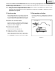
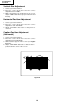
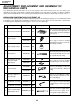
Mechanical setting:
Turn the loading motor’s pulley feed gear using a
screwdriver and be sure that the mechanism is back
to its initial setting position (*1). Now place the
cassette controller in position.(This method is appli-
cable for the mechanism alone.)
Pulley feed gear
Screwdriver
Large tooth
Casecon
drive gear
Drive angle of
cassette control
PRECAUTIONS IN REASSEMBLING
MOUTING THE CASSETTE CONTROLLER
Initial setting is indispensable before placing the cassette controller in the mechanism. The initial setting is made in two
ways;electrical and mechanical.
Electrical setting:
Make a short-circuit between TP7701 and TP7702 and be sure that the mechanism is back to its initial setting position (*1).
Now place the cassette controller in position.(This method is used when the mechanism has been already set on its PWB.)
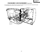
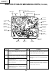
COUPLING THE MECHANISM TO THE PWB
Match the mechanism’s projections with the two symbols (round reference and oval sub-reference) on the main PWB. Place the
mechanism straight down in position with due care so that the mechanism chassis’s outer edges should not damage any parts
nearby.
Tighten up the two screws (one for fixing the mechanism and the head amplifier shield, the other on the main PWB’s soldering side
and located near the loading motor) to fix the mechanism and main PWB. Reconnect the FFC cables (MH and AA, ME and AD,
Drum Unit and AH) between the mechanism and main PWB.
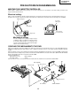
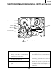
Parts to pay attention to:
Start and end sensors Q7703, Q7704
Record tip switch S7701
Take special care of the connectors (board to board; AC, AE, AL) between the mechanism and main PWB.
END SENSOR
REC TIP SW
AL Connector
AE Connector
AC Connector
START SENSOR