9SV111 SHARP SERVICE MANUAL S99N919SV1 111 GAME TElEVISION SIGMA 9400 CHASSIS Chassis No. 19M1 MODEL 19SV111 In the interests of user-safety (Required by safety regulations in some countries) the set should be restored to its original condition and only parts identical to those specified should be used. c~~ L'QIV/IliU ~ Q '?, 0 c.. N1 '2DZ.
'19SV111 IMPORTANT SERVICE SAFETY PRECAUTION • Service w_ork should be performed only by qualified service technicians who are thoroughly familiar with all safety checks and servicing guidelines which follow: 2. It is essential that servicemen have available at all times an accurate high voltage meter. The calibration of this meter should be checked periodically. 3. High voltage should always be kept at the rated value -no higher.
19SV111 IMPORTANT SERVICE SAFETY PRECAUTION (Continued) safety characteristics are ide nti fi ed in this manual; electrical components having such features are identified by ".&"and shaded areas in the Replacement Parts Lists and Schematic Diagrams. For continued protection, replacement parts must be identical to those used in the original circuit.
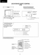
19SV111 LOCATION OF USER'S CONTROL (TV) IAntenna Terminal Board I Front (Located on the rear of the cabinet) r--__;l-l1111 ----#-CHANNEliNDICATOR E,;~ COAXIAL CABLE ~ "~ 1 r----+T-1 ----H- SENSOR AREA FOR REMOTE CONTROL b ~ _lr--f++--+1- MEMORY INDICATOR '-----~-'-Lf= ~1~~-;;~.SI~~;.~?" ~_. . . . ,~;. -l =POWER ON-OFF BUTION l . b ~ ee J C?..;~~ 1~I~ ~ Control Access Door L ~ bJ~~~~~~~~~n•l t L~.o-~ . VOLUME ADJUSTMENT BUTTONS o== _ o=.,.
19SV111 LOCATION OF USER'S CONTROL (Continued) (GAME) I Front Controller CONTROL PAD START BUTTON BUTTON B - - - - ' GAME ON/OFF BUTTON A - - - - - - ' CONTROLLER PLUG CONTROLLER SOCKET 1 CONTROLLER SOCKET 2 CONNECTING THE CONTROLLERS TO THE TV Both controllers are identical and may be connected to either controller socket.
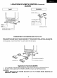
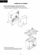
19SV111 REMOVAl OF CABINET How to detach the game unit from the TV set 1. Unscrew the six rear cabi net set-screws and remove the rear cabinet. 2. Disconnect the game unit connectors (EB, N, V, A and EA) from the TV set. 3. Place the TV set upside down. 4. Unscrew the four game unit set-screws from the TV set. Now the game unit can be detached from the TV set .
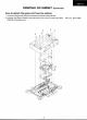
19SV111 REMOVAL OF CABINET (continued) How to detach the game unit from the cabinet 1. Unscrew the eight top cabinet set-screws and remove the top cabinet. 2. Unscrew the eleven shielding case set-screws and the four chassis set-screws. (PWB-D) can be drawn out.
19SV11 'I INSTALLATION AND SERVICE INSTRUCTIONS Note: (1) When performing any adjustments to resistor controls and transformers use non-metallic screwdriver or TV alignment tools. (2) Before perfoming adjustment, TV set must be on at least 15 minutes. CIRCUIT PROTECTION HIGH VOLTAGE CHECK The receiver is protected by a 4.0A fuse (F701), mounted on PWB-A, wired into one side of the AC line input.
19SV111 INSTALLATION AND SERVICE INSTRUCTIONS (Continued) FIELD ADJUSTMENT NOTE 1: All field adj-Ustments mentioned can be performed without test equipment. NOTE 2: As this model has "Built in AFT", AFT is always in "ON" position. If AFT should be "OFF", short between TP1003 and • RF-AGCADJUSTMENT 1. Select a local channel. 2. Turn RF-AGC control (R214) fully ciO
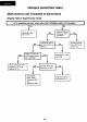
195V111 TROUBLE SHOOTING TABLE Malfunctions not Traceable to Game Deck Display Fails to Appe-a (o.nly noise) I Is TV operation normal, when select the TV/GAME switch to TV position? No Yes \ ~ r---··---, 1Check the Lead 1Wire "oc•. ' lr I 1 No L-------J Is there DC 1OV at ....N_o_.....,. pin (1) of IC101 on PWB-E? Is there DC SV at Connector "EC1" on PWB-E? Yes '~ r-- -· ... -- -, Check the T1 01 AC r--No_---1 120V supply {Across EA 1 and EA2)? Yes I Check IC101, C107 I I I and C108.
19SV111 TROUBLE SHOOTING TABLE (Continued) Controller Doeswt Function. Is problem corrected by replacing controller ? Yes No Game Deck faulty. Controller faulty. Selection and starting not possible or selection mark continues moving. Pause occurs during game or pause occurs when button A pressed during game. Some buttons don't operate or some buttons remain ON. Are controller socket pins and harnesses (PWB-G) OK? Controller cord faulty.
19SV111 TROUBLE SHOOTING TABLE (Continued) Malfunctions Traceable to Game Deck * Prior to replacing parts: Check the following items before referring to the tables on the following pages and repairing the Game Unit. 1. Check the contact condition of card connector 72P. 2. Check the soldering of all parts. 3. Visually inspect for short circuits. 4. Check that all parts are mounted correctly. 5. Check for ICs that heat up abnormally while power is on (other than ICS PPU). 6.
19SV111 TROUBLE SHOOTING TABLE
19SV111 TROUBLE Symptom SHOOTI~G TABLE
19SV111 TROUBLE SHOOTING TABLE ccontinued) Symptom Repair Procedure Location of Fault (in order of probability) Display Normal, But Sound Abnormal 1. Is there faulty soldering cr a break in the Abnormal melody. No sound. conductor pattern in R3, R4, R6, R7 or RS; Faulty IC6 CPU. 1. Is there faulty soldering or a break in the conductor pattern near IC9, C23, QS, R21, (48 or FC1? 2. Is IC9 faulty ? 3. Are there breaks in the conductor pattern near the audio signal circuit? 4. Faulty IC6 CPU.
J> ,.. m 0 " 0> I C\ PWB- 9 F4784PE PWB- H F6537PE cCJ ~l.A~t oe~ o • • • oe~l B 01~ ~8 ~ PWB-G F6532PE PWB- F F6531 PE "" [•~0 102 • ~ col n1 n nasw1o2 ~il£S£T ~"U sw•o •• CHI~~ l PWB-A F507 1PE SW IIO) w SW 1 HJ6 _. ~ RIC P(IW[R oeU SW1t04 = •• 0 1201 REI:EJV(Q I II 0 11103 $ W1102 N 0 IC J20 t ~ I • 1 o oeo o I • I Jc t t>o t 0 ~ )t i ~O I I • •• .
19SV111 PRINTED WIRING BOARD ASSEMBLIES H G PWB-H W iring Side PWB-B Wiring Side F E D PWB-F Wiring Side PWB-G Wiring Side c 00 B 0000 A PWB-E Wiring Sid e 2 3 4 17 5 6
19SV111 PRINTED WIRING BOA.RD ASSEMBLIES H G [1fiD ~~?-~-~ F te. :? __,..,..;.,...,.,.,...;.--__. .....
SV111 PRINTED WIRING BOAR.
19SV111 19SV111 BLOCK DIAGRAM PWB-A VARACTOR TUNER BAND V T V-SIZE TINT COLOR PICTuRE { PWB-8 R-Y 0201 IF Pfl(AMP 0 EX T J CONTROL J IC1401 ~t--rv OE:COOER "'"' .~>DORESS t - - - - - - 1 ~t--~ ..___..__ r-r-- - _]., F t- sw I ~ I v 0405.6 VIDEO ~ A'JJI' IC!> PPU L404 DELAY LINE D i C7.JC8 BUfFER -LJ-..
19SV111 BlOCK DIAGRAM (continued) IC 1 and IC4: R H - i X 1 2 4 5 C E Z Z H PIN_S ARRANGEMENT Pin Function Address Input Ao-A, G cs Chip Select OE Output Enable WE Write Enable F tO A() 2 As A4 A3 3 4 5 A2 A, Ao 11 o, Data l nput I 0 utput 1/0 1 -l/Oa Az l/02 Vee Power 1/03 GND Ground GND 24 23 Vee 22 Ag WE OE 6 21 20 19 7 18 bo cs 8 9 17 1/0s 16 15 14 l/Oz l/06 l/Os l/04 10 11 12 Aa 13 BLOCK DIAGRAM E Ao As A6 Az As Ag D A,(j cv®--®---- 0®-CfP®--- ~
19SV111 BLOCK DIAGRAM (Continued) IC2: RH-iX0666CEZZ Output Control Input oc .... Output 1Q +- SQ Data { 10 -so ~ 70 Output Control Input Output }Data Input -7Q} rQ Output .... 6Q 3Q -+ 60 Data {3D Input oc E Vee Input . 20 Output Enable Input 40 } Data Input -+50 ~ Output 4Q Output SQ Data Input Enable Input GND PINS ARRANGEMENT Output IC3: R H - i X 0 3 4 1 C E Z Z Enable Input 1f ..... Vee fDA Input Output .-2f 1Da .
19SV111 BLOCK DIAGRAM H ICS: (continued) RH~iX0822CEZZ IC6: R H - i X 0 8 2 1 C E Z Z Vee Vee DBO ALE DBO ALE DB1 ADO DB1 ADO D82 AD1 D82 AD1 DB3 AD2 DB3 AD2 DB4 AD3 DB4 AD3 DBS AD4 DBS AD4 DB6 ADS DB6 ADS DB7 AD6 DB7 AD6 R52 AD7 R52 AD7 RS1 AB RS1 AB RSO A9 RSO A9 DBE A10 DBE A10 EXTQ A11 EXTO A11 EXT1 A12 EXT1 A12 EXT2 A13 EXT2 A13 EXT3 RD EXT3 RD CLK WR CLK WR INT RESET INT RESET GND VIDEO GND VIDEO G f E D PINS ARRAN
19SV111 SOLID STATE DEVICE BASE DIAGRAM B B c c E E E 0 c c G E B s B K G A r-----~~--~----~--~----~---------~-----~~-, TOP VIEW 11 16-9 c::::::: :I c::::::1 10 ~~:::::::::::1 1 1] I 10 1(1 1(4 1-6 ICJ IC2 ---~o 16-9 >::::::::1 1-s IC7 14-8 a 16-9 s- s 6----.
19SV11 1 Memo 27
19SV111 DESCRIPTION OF SCHEMATIC DIAGRAM NOTE: 7. The unit of resistance ..ohm .. is omitted (K: 1000 ohms, 2. 3. 4. 5. 6. M : 1 Meg ohm). All resistors are 1/8 watt, unless otherwise noted. All capacitors are pF, unless otherwise noted P:ppF. (G) indicates 1:2% tolerance may be used. .:;. indicates line isolated ground. -Qo indicates hot ground. VOLTA GE MEA SUREMENT CONDITIONS: 1.
19SV111 19SV111 MAIN-2 CIRCUIT This circuit diagram is a standard one, printed circu its may be subject to change for product improvement w ithout prior notice. H --~ ~ (2/2) ·...j·........·......·-!··-rL. j G 100 ooo ooo ~~~ros ·".E.> o•~• 100 •00 ' 00 •uw »o a..o a no XWOOI!o!.IC •oHO ,...!10)' ""' 11W ..... _ ..... lhUI IIIU 104 uo sea =~ =~tnrr4~~« :: turo. I)J ,roo.. ~o---------~.~.1 ... • H 06 ------ ----1 -----·-r -1 .. : PWB-A OM11(!.0'11W(V7'1 I Q \1.
H lSV111 19SV111 This circuit diagram is a standard one, .printed circuits may be subject to change for product improvement without prior notice. MAIN-1 CIRCUIT IIIIP'\.Atl(wrtlol .t. ~ &MC.......,. ,.CIA rc fl' M CGWT...
19SV111 GAME CIRCUIT PWB-H 19SV111 This circuit diagram is a standard one. printed circuits may be subject to change for product improvement without prior notice. PWB-E .----------------------------------------------------------------, ! f H I I i i 1 ~!em H. ~· ~ ~ ~? ~ 1 <-~ , m; G ! ! GAME CONTROLLER ~ ;.~ : l I :..~ . _., 4021 ""'=----t ""' --t ""- ..j TO PwO--A W 1 +t lb ,- ------ -- -~~C!'..'~!l- !~-~·! -- - , . ~COZS2C'E'Tl . . . . Xof.
19SV111 REPLACEMENT PARTS LIST <.& ) SAFETY NOTE - Components marked with a nave special characteristics important to safety. Before replacing any these components, read carefully the SAFETY NOTICE on page 3 of the Service ManuaL Components marked with an (A) are related to X- Ray Protection circuit. HOW TO ORDER REPLACEMENT PARTS -To have your order filled promptly and correctly, please furnish the following information: 2. PART NO. 1. MODEL NO. 3.
19SV111 Ref. No. Part No. Description I II Code Ref. No. RH -OX 0 0 4 5 GEZZ 406, or 410, VHD1SS1 19/f1E J 1 N4148 AA blD707 A6 RH -DXO 1 6 1 CEZZ J RGZV AE J EU-lV AD AGP10J AC or J 1SS1 19 AA RH -DXO 2 0 2 CEZZ or 601, Al Description DIODES (Continued) DIODES 0401, Part No. 2 2 6 (EZZ 610, ,1\0708 RH -DXO 1 31 CEZZ 612, 0710 RH -E XOO 2 1 TAZ.Z RH-E X004 7 CEll J J J J RH -E X 0 2 1 7 CEZZ RH -OX 0 606, 613, 0713, 709, 1613 712, 01151. 714, 1152, 801.
19SV111 Ref. No. Description Part No. ICode Jl Ref. No. CAPACITORS COILS L202, VP .- R F R-8 2 K 0000 lleKription Part No. j 0.82].!H (209, AS VCEAGA 1CW33 7M j 16V 330 317, 203 L205 VP -MKR 5 6 MOOQO J 0.56].!H AB 319, L206 RC i L i 04 7 3 CEZZ J PIF Detector AD L207 RCili0510CEZZ J AFT AF 432, 444, 1204, L303 RC i L i 0 3 7 4 CEZZ J Sound Detector AD L40 1, VP -X F 1 0 0 K 0000 J 10JJH AB 1308, 1616 601, C335.
19SV111 Ref. No. Description Part No. I Code II RESISTOkS ,& R448 VRS -VV 3AB 1 2 3 J J Ref. No. VRS -VV 3 LB 2 7 0 J J AA 12k 1W 27 3W AB Oxide Film .6,&. R_614 VRD-RA 2 BB9 3 J J 39k 1/BW Carbon A&_R615 VRD-RA 2 BE 1 2 3 J J 121r. 1/BW Carbon AA AA .6.& R616 VRD-RA 2 BE 56 2 J J 5.6k 1/SW Carbon AA A&_ .VRD-RA2BE1 53J J 15k 1/8W Carbon AA .&, R702 VRW-KV3NC 2 R 7 K J 2-7 7W AC _.
I Ref No. 1•1 Part No. Description jcode jj Ref. No. C653 INTEGRATED CIRCUITS AH- i X 0 3 59 CEZZ .&..!h_IC752 AH -F XO 0 03 CEZZ J J I• I Desuiptlon CAPACITORS PWB-C DUNTK4783WEV9 POWER REG. UNIT .&&,1C751 Part No. 19SV111 VCEAG.A.1 EW 107M J 100 25V AD Electrolytic AL ~C656, AK ~ 657, A& VCF PPD 3CA 222 J J 0 .00221.6kV AD Metalized Potyster 65S C659, VCK YPA2HB 471 K J 470p soov AA Ceramic 757, 759, TRANSISTORS 0651 .6.
19SV111 Description Part No. Ref. No. I II code Ref. No. RESISTORS R654 VRS - W 3 LB 3 9 0 J J TRANSISTORS 39 3W AB OxideFiim JS::.. R655 VRN- VV 3ABR 3-3 J J 0.33 1W ,& R656, VRN - W 3AB 1 R 0 J J 1 VRS - VV 3DB 3 3 1 J J 330 2W AA Metal Coating ih lW Q1 VS 2SA 1 0 1 S Y /-1 AC VS 2SC2 3 OS C/-1 J J 2.SA101S(Y) Q2, 2SC2308 AB VS 25(94 5 AQ 1-1 J 2SC945A(Q) AB 3 04. AA 5 Metel Coating 661 &_ R657 Description Part No. AA Oxide Film ,£.
19SV111 Ref. No. I* I Part No. Description [code [[ PWB-F PWB-E DUNTK6530WEVO SUB POWER UNIT VH i HA 17805 W- 1 J Description DUNTK6531 WEVO SWITCH UNIT INTEGRATED CIRCUIT IC101 [* I Part No. Ref. No.
19SV111 Ref. No. Part No. Description Icode II CABINET PARTS Ref. No. 3 Part No. CCABB 2 0 8 B WEVO Description R Cabinet Complete BT -Bottom {Game) 1 CCABA 2 0 9 6 WEVO R Cabinet BV 3-1 Not Available - -Front Cabinet - -Bottom (Game) Cabinet -Front - 3-2 GCOVAOO 3 5 PEKA R Cov-er AF 1-2 GDOR FO 0 96 PEKA R Door AP 3-3 G LEGP 9 0 0 1 PEKA R Leg.
19SV111 Ref. No. Description Part No. RRMCG0683CE SA GAME CONTROLLER 1 9SJ56-6106·C J Controller Cabinet. AL Top (WI Controller Overlay) 2 95156-7578-C J Controller Cab1net, 3 95J56-7579-A J Control Pad AE Bottom AC Actuator 4 95J56-0899-B J AlB Button 5 95156-7598-C J Controller Cable AA Actuator AX (W/7P Plug) 6 95J56-0900-A J AJB Button Contact AD 7 95J56-8233-C J Control Pad .O..
19SV111 PACKING OF THE SET • Setting positions of the knobs s 110 Brightness control .-----1* 5/10 Color control 1.----1* Best position Tint control Poctu1e cont1ol TCAUH0011PEZZ Salety Card TGAN-001BPEZZ Guarantee Card 10/10 ~---1* T i NS-4Z60PEZZ TV I CATV swotch TV Aging switch OFF Operation Manual Relea~e Cassette Holder ,.~ ":._~ t Game Controller Infrared Remote Controller and Dry Batter1es (2 pes.