21HS-50H SERVICE MANUAL SEBD21HS50H01 Issued: 24th October 2001 GA-1E CHASSIS PAL I SYSTEM COLOUR TELEVISION MODEL 21HS-50H In the interests of user safety (required by safety regulations in some countries) the set should restored to its original condition and only parts identical to those specified should be used. CONTENTS ELECTRICAL SPECIFICATION.........................3 IMPORTANT SERVICING NOTES ...................4 CONTROLS & TERMINALS..............................5 SERVICE ADJUSTMENTS...........
1HS-50H SERVICE MANUAL UPDATE LOG SHEET Technical Report No. Technical Bulletin No. Cause / Solution Part No. Page No. Application Data /Serial No. Use this page to keep any special servicing information as Technical Report (Bulletin), Technical Information, etc. If only part number changes are required, just change part number directly the part number in the Parts Listing Section. If you need more information, please refer to the Technical Report (Bulletin).
21HS-50H ELECTRICAL SPECIFICATIONS •Sound Carrier Trap...............................32.9MHz •Power Input .......................220V-240 Volts AC 50Hz •Power Consumption Normal Operation....................................43W Stand-by Operation...................................3W •Adjacent Sound Carrier Trap.................40.9MHz •Audio Power Output Rating ................4W x 2(MPO) •Adjacent Picture Carrier Trap...............30.9MHz Speaker................................
21HS-50H IMPORTANT SERVICING NOTES Only qualified service personnel are allowed to carry out maintenance and repair of this receiver. SERVICING OF HIGH VOLTAGE SYSTEM AND CRT It is important that the static charge is removed from the high voltage system when carrying out work on the receiver. This can be achieved by connecting a 10K resistor (with a suitably insulated lead) from the CRT cavity connector to the CRT ground tag. This must be carried out with the AC supply disconnected from the receiver.
21HS-50H Location of Controls Remote Control CALL ( )/CHILD LOCK ( Infrared Transmitter Window Aim this window at the infrared sensor on your TV set ) button TV/VIDEO Select button TV POWER/STANDBY ( TV/VIDEO VCR Single/Double Entry button ( ) button Programme Select buttons VOLUME UP ( )/DOWN ( ) buttons ( ) Increases sound ( ) Decreases sound (These are also used for menu set up) 3 COLOUR buttons 5 6 8 9 CHANNEL (PROGRAMME) UP ( )/ DOWN ( ) buttons ( ) Selects next higher programme ( )
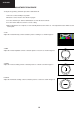
21HS-50H SERVICE ADJUSTMENT • SERVICE MODE FUNCTION • All required adjustments for servicing this TV set, may be done in “service mode”, excepting G2 and FOCUS. HOW TO ACCESS THE SERVICE MODE 1. Turn the receiver on and ensure that it is tuned into a test pattern. 2. Turn the receiver off using the mains switch. 3. Press the volume down and channel up buttons together. See Fig.1. 4. Continue pressing the volume down and channel up buttons while turning the mains on using the mains switch. See Fig.
21HS-50H • SERVICE ADJUSTMENTS AND DATA LIST The table below shows the various service mode positions, range of values and default value. The columns are headed as follows. Heading: Description: OSD This is what will appear on the screen when at this position Function This is the description of the mode’s function Range This is the range of values that can be entered while in this mode Initial This is the initial value, i.e.
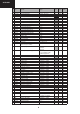
21HS-50H No. OSD Function Range Initial Default 25 26 27 28 29 30 31 32 33 34 35 36 37 38 39 40 41 42 43 44 45 46 0...63 0...99 or > 99 for none 0...15 0(L-BG),1(BG),2(I),3(DK) 0...63 0...63 0...15 0...15 0...15 0...15 0...15 0...15 0...15 0...15 0...15 0...15 0..255 0..127 0..127 0..127 0...3 data(1.2.4.8.) 0..
21HS-50H • SCREEN ADJUSTMENT 1. G2 Adjustment 1. Enter the service mode (see page 6). 2. Use the channel up or channel down buttons to enter the << BLUE-BACK >> function. 9GF 3. Set this to << BLUE-BACK: 0 >>, i.e. blue background is turned off. 4. Turn the set off at the mains. 5. Turn the set back on. 6. Set the picture control settings to normal. 7. Select the SCART input by pressing the TV/SCART button on the remote control. Do not connect an input to the SCART socket.
21HS-50H • GEOMETRY ADJUSTMENT PROCEDURE To adjust the geometry, follow the procedure outlined below: 1.Tune the set into a Philips test pattern. 2.Enter the service mode as described on page 6. 3.Use the channel up or channel down buttons to enter the desired mode 4.Use the volume buttons to achieve correct setting. 5.When adjustments are complete, use the standby button to turn off the set. The adjustment values will be stored at this point.
21HS-50H •COLOUR ADJUSTMENT PROCEDURE The following adjustments should only be carried out when the CRT or IC801 are replaced. NOTES: • This adjustment must be done after warming up the unit for 30 minutes or longer with a beam current over 700 µA. • The red value «DRI-RS» should be fixed to 42. (Refer to “How to access service mode” section). • «DRI-GS» adjustment alters “Y” co-ordinate. • «DRI-BS» adjustment alters “X” and “Y” co-ordinates.
21HS-50H CHASSIS LAYOUT MOTHER UNIT CRT UNIT 12
21HS-50H LED FLASHING CODE The led indicates the power mode,ocurred I2C error and On timer PURPOSE: INPUT: - Current power mode - I2C Errors - On timer Processing: - If in STANDBY mode and On timer in-active then switch LED off. - If in STANDBY and On timer active set LED to blinking, (switch on and off at 1 Hz with a 50 % duty cycle). - If in POWER-ON mode, switch LED on. - If an I2C error occurred, let the LED blink at 1 Hz, 50 % duty cycle. For the blinking times see the Table below.
21HS-50H F 7340N4 PRINTED WIRING BOARD. Components side.
21HS-50H F 7340N4 PRINTED WIRING BOARD. Components side.
21HS-50H F 7340N4 PRINTED WIRING BOARD. Copper side.
21HS-50H F 7340N4 PRINTED WIRING BOARD. Copper side.
21HS-50H ICs ADDITIONAL INFORMATION:TDA9350(IC801) QUICK REFERENCE DATA SYMBOL PARAMETER MIN. TYP. MAX. UNIT Supply VP supply voltages − 8.0/3.3 − V IP supply current − 135/60 − mA ViVIFrms) video IF amplifier sensitivity (RMS value) − 75 − µV ViSIF(rms) QSS sound IF amplifier sensitivity (RMS value) − 60 − µV Input voltages ViAUDIO(rms) external audio input (RMS value) − 500 − mV ViCVBS(p-p) external CVBS/Y input (peak-to-peak value) − 1.
42 40 24 19 +8V 37 38 15 19 14 39 18 41 30 SNDIF REF VIDEO FILTERS VIDEO IDENT. VIDEO SWITCH VISION IF ALIGNMENT-FREE PLL DEMOD. AGC/AFC VIDEO AMP. 27 17 H-OSC. + PLL H/V SYNC SEP.
21HS-50H ICs ADDITIONAL INFORMATION:TDA9350(IC801) PINNING SYMBOL PIN DESCRIPTION P1.3/T1 P1.6/SCL P1.7/SDA P2.0/TPWM P3.0/ADC0/PWM0 P3.1/ADC1/PWM1 P3.2/ADC2/PWM2 P3.3/ADC3/PWM3 VSSC/P P0.5 P0.
HS-50H ICs ADDITIONAL INFORMATION:TDA9350(IC801) SYMBOL INSSW2 R2/VIN G2/YIN B2/UIN BCLIN BLKIN RO GO BO VDDA VPE VDDC OSCGND XTALIN XTALOUT RESET VDDP P1.0/INT1 P1.1/T0 P1.
21HS-50H ICs ADDITIONAL INFORMATION:TEA1507(IC701) ndbook, full pagewidth VCC 1 SUPPLY MANAGEMENT 8 START-UP CURRENT SOURCE clamp internal UVLO start supply GND 2 S1 7 VALLEY DRAIN HVS n.c. M-level 4 VOLTAGE CONTROLLED OSCILLATOR LOGIC DEM 100 mV OVERVOLTAGE PROTECTION FREQUENCY CONTROL OVERTEMPERATURE PROTECTION CTRL LOGIC 6 DRIVER DRIVER Iss 3 −1 POWER-ON RESET S Q R Q LEB blank UVLO 2.5 V 0.
21HS-50H ICs ADDITIONAL INFORMATION:AN7523(IC303) 9 Volume 8 Pin Descriptions N.C. 7 GND 6 Input 5 Standby 4 GND Output 3 2 Output VCC 1 Circuit Function Block Diagram Pin No. Description 1 Vcc 2 Ch Output (+) 3 GND 4 Ch Output (-) 5 Standby 6 Ch Input 7 GND (Input) 8 N.
21HS-50H ICs ADDITIONAL INFORMATION:MSP34x5G (IC3001) Absolute Maximum Ratings Symbol Parameter Pin Name Min. Max. Unit TA Ambient Operating Temperature – 0 70 °C TS Storage Temperature – −40 125 °C VSUP1 First Supply Voltage AHVSUP −0.3 9.0 V VSUP2 Second Supply Voltage DVSUP −0.3 6.0 V VSUP3 Third Supply Voltage AVSUP −0.3 6.0 V dVSUP23 Voltage between AVSUP and DVSUP AVSUP, DVSUP −0.5 0.
21HS-50H ICs ADDITIONAL INFORMATION:MSP34x5G (IC3001) NC DACM_L VREF1 DACM_R SC1_OUT_R SC1_OUT_L VREF2 NC NC AHVSUP NC 33 32 31 30 29 28 27 26 25 24 23 CAPL_M 34 22 RESETQ AHVSS 35 21 I2S_DA_IN2 AGNDC 36 20 DVSS SC2_IN_L 37 19 DVSUP SC2_IN_R 38 18 ADR_CL ASG 39 17 I2S_DA_IN1 SC1_IN_L 40 16 I2S_DA_OUT SC1_IN_R 41 15 I2S_WS VREFTOP 42 14 I2S_CL MONO_IN 43 13 I2C_DA AVSS 44 12 I2C_CL MSP 34x5G 1 2 3 4 5 6 7 8 9 10 11 AVSUP STANDBYQ ANA_IN1+ A
21HS-50H DESCRIPTION OF SCHEMATIC DIAGRAM NOTE: 1. The unit of resistance «ohm»is omitted (K=1000 ohms. M= Megaohm). 2. All resistors are 1/16 watt. unless otherwise noted. 3. All capacitors are µF, unless otherwise noted (P= µµF). 4. The capacitor with Part No. RC-FZ9XXXBMNJ is designed to with stand 63V. 5. The capacitor with Part No. RC-FZ4XXXBMNJ is designed to with stand 50V. SAFETY NOTE: 1. DISCONNECT THE AC PLUG FROM THE AC OUTLET BEFORE REPLACING PARTS. 2.
21HS-50H 27
21HS-50H SCHEMATIC DIAGRAM OF MOTHER UNIT (F7340N4, 01 Version) I H G F E D C B Page 29 A 1 2 3 4 28 5 6 7
21HS-50H SCHEMATIC DIAGRAM OF MOTHER UNIT (F7340N4, 01 Version) I H G F E D C B Page 28 Page 30 A 8 9 10 11 29 12 13 14
21HS-50H SCHEMATIC DIAGRAM OF MOTHER UNIT (F7340N4, 01 Version) I H G F E D Page 29 C B A 8 9 10 11 30 12 13 14
21HS-50H SCHEMATIC DIAGRAM OF CRT (F7341N0, 00 Version) I H G F E D C B A 1 2 3 4 31 5 6 7
21HS-50H CRT UNIT BLOCK DIAGRAM I H G F E D C B A 1 2 3 4 32 5 6 7
21HS-50H MOTHER UNIT BLOCK DIAGRAM I H G F E D C B A 1 2 3 4 33 5 6 7
21HS-50H TROUBLESHOOTING TABLES. NO RASTER Check F701. Blown out. Abnormal Normal Replace the fuse. Check R701 Q701. and IC701 Check T701 pin16 voltage. (Approx. 290V at 220V AC) The fuse is again blown out. Check IC701,D701,D702, D703,D704 and C705. Normal Abnormal Check Secondary Main+B. (Approx. 110V) Check D758,IC702,IC753 and D762. Check CRT connector K1K5 bias. YES Normal Normal Abnormal Check R615. Check C878. Check IC801. D1001 (Power LED Bright Red) turns on.
21HS-50H TROUBLESHOOTING TABLES. NEITHER VERTICAL NOR HORIZONTAL SYNCHRONIZATION CIRCUIT TO BE CHECKED: Sync. Separator Circuit. Check pin33 and 34 of IC801. DEFECTIVE VERTICEL AMP. AND VERTICAL LINEARITY Readjusted vertical size. (Bass Data) Vertical linearity and size is abnormal. Check R502,R505 NO VERTICAL SCAN Check IC501 bias. Normal Abnormal Check C502 and C514. Check IC501.
21HS-50H TROUBLESHOOTING TABLES. NO PICTURE, NO SOUND CIRCUITS TO BE CHECKED: Tuner. PIF. Automatic Gain Control. 5V, 32V Power Source. Does the noise level increase at max. Contrast,Brightness and Sound controls? Noise increase but no signal is received. No snow noise. Check the tuner supply voltage LB and HB must be approx. 5V, BT must be approx. 32V,and CH preset data check.
21HS-50H PARTS LISTING REPLACEMENT PARTS Replacement parts which have special safety characteristics are identified in this manual. Electrical components having such features are identified by in the Replacement Part List. The use of a substitute replacement part which does not have the same safety characteristics as the factory recommended is not permitted. Replacement parts not shown in this service manual may create shock fire, or other hazards.
21HS-50H REF No.
21HS-50H REF No.
21HS-50H ! REF No.
21HS-50H REF No.
21HS-50H DOCUMENTATION OF SOURCES. 1. TDA9350, Philips Data Sheet: TDA935X/6X/8X PS/N2 series, TV signal processor-Teletext decoder with embedded µ-Controller. Tentative Device Specification, 2001 Aug 29, Version: 2.9. 2. TEA1507, Philips Data Sheet: TEA1507 GreenChipII SMPS controlIC. Preliminary specification, 2000Dec05. 3. AN7523, Matsushita Electronics Corporation Specifications: AN7523 Product Specifications. Doc No. SDSC-PSE-AN7503, Eff. Date 23-FEB-01. 4.
21HS-50H NOTES: 43
21HS-50H No part of this publication may be reproduced, stored in a retrieval system, or transmitted in any form or by any means, electronic, mechanical, photocopying, recording, or otherwise, without prior written permission of the publisher. SHARP ELECTRONICA ESPAÑA S.A. TV Division Engineering Dept.