
Service manual


8
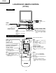
IC2001
IC2102
X
IC3001 X
IC201
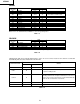
Data is stored in IC2102.
Adjust items related MTS only.
Holding down both the Vol-up/Ch-down buttons on the TV set at service mode for more than 2 seconds will
automatically write the above initial values into IC2102.
Table - E
The adjustment is needed to compensate for characteristics
of parts including IC201.
Holding down both the Vol-up/Ch-down buttons on the TV set
in the service mode for more than 2 seconds will automatically
write the above initial values into IC2102.
X
X
ADJUSTMENT
NECESSARY
UNNECESSARY
PART REPLACED
NOTES
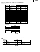
SIGNAL
S01 RF AGC 00-3F 14
S02 VIDEO LEVEL 00-07 03 Must be "4"
S03 Y-MUTE 00-03 00
"01": Y-MUTE, "02": V-STOP & Y-MUTE
"03":
Activate color killer circuit.
S04 SUB BIAS 00-FF 30 Must be "30"
S05 R-BIAS 00-FF 00
S06 G-BIAS 00-FF 00
S07 B-BIAS 00-7F 00
S08 R-DRIVE 00-7F 53
S09 B-DRIVE 00-7F 53
S10 CONTRAST 00-7F 5A
S11 TINT 00-7F 40
S12 COLOR 00-7F 40
S13 BRIGHTNESS 00-7F 40
S14 BRIGHTNESS 2 00-7F 40
SERVICE
POSITION
ADJUST ITEM
DATA
RANGE
INITIAL VALUE
ADJUSTMENT CONTENTS
Note: Refer to the SERVICE ADJUSTMENT for each corresponding values.
Table - C
M01 MS LEVEL 00-0F 0A
M04 LOW SEPARATION 00-3F 20
M05 HIGH SEPARATION 00-3F 1B
SERVICE
POSITION
ADJUST ITEM
DATA
RANGE
INITIAL VALUE
ADJUSTMENT CONTENTS
Table - D
FEATURE
Note: Refer to the SERVICE ADJUSTMENT for each corresponding values.
CRT X
Adjust items related to picture tube only.
27C240