PN-K321 LCD MONITOR OPERATION MANUAL
IMPORTANT: To aid reporting in case of loss or theft, please record the product’s model and serial numbers in the space provided. The numbers are located in the rear of the product. Model No.: Serial No.: U.S.A.
IMPORTANT INFORMATION WARNING: TO REDUCE THE RISK OF FIRE OR ELECTRIC SHOCK, DO NOT EXPOSE THIS PRODUCT TO RAIN OR MOISTURE. CAUTION RISK OF ELECTRIC SHOCK DO NOT OPEN CAUTION: TO REDUCE THE RISK OF ELECTRIC SHOCK, DO NOT REMOVE COVER. NO USER-SERVICEABLE PARTS INSIDE. REFER SERVICING TO QUALIFIED SERVICE PERSONNEL.
DEAR SHARP CUSTOMER Thank you for your purchase of a SHARP LCD product. To ensure safety and many years of trouble-free operation of your product, please read the Safety Precautions carefully before using this product. SAFETY PRECAUTIONS Electricity is used to perform many useful functions, but it can also cause personal injuries and property damage if improperly handled. This product has been engineered and manufactured with the highest priority on safety.
SAFETY PRECAUTIONS (Continued) WARNING: This is a class A product. In a domestic environment this product may cause radio interference in which case the user may be required to take adequate counter measures. To maintain compliance with EMC regulations, use shielded cables to connect to the following terminals: HDMI input terminal and DisplayPort input terminal. If a monitor is not positioned in a sufficiently stable location, it can be potentially hazardous due to falling.
TIPS AND SAFETY INSTRUCTIONS - The TFT color LCD panel used in this monitor is made with the application of high precision technology. However, there may be minute points on the screen where pixels never light or are permanently lit. Also, if the screen is viewed from an acute angle there may be uneven colors or brightness. Please note that these are not malfunctions but common phenomena of LCDs and will not affect the performance of the monitor.
MOUNTING PRECAUTIONS • This product is for use indoors. • A mounting bracket compliant with VESA specifications is required. • To install on a stand (commercially available) or on a wall, or to remove or move the monitor, consult your dealer. • Mounting the monitor on the wall requires special expertise and the work must be performed by an authorized SHARP dealer. You should never attempt to perform any of this work yourself.
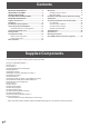
Contents IMPORTANT INFORMATION.............................................3 DEAR SHARP CUSTOMER...............................................4 SAFETY PRECAUTIONS...................................................4 TIPS AND SAFETY INSTRUCTIONS................................6 MOUNTING PRECAUTIONS.............................................7 Supplied Components......................................................8 Part Names........................................................................
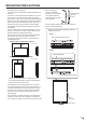
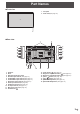
Part Names nFront view 1. LCD panel 2. Power LED (See page 15.) 1 2 nRear view 1 2 4 13 14 15 16 17 18 19 5 6 7 8 9 10 11 1. 2. 3. 4. 5. 6. 7. 8. 9. 10. 11. 12. Speakers Vents Attachment plate (for stand) RS-232C input terminal (See page 12.) PC/AV HDMI 1 input terminal (See page 12.) PC/AV HDMI 2 input terminal (See page 12.) DisplayPort input terminal (See page 12.) Audio input terminal (See page 12.) Headphone terminal (See page 12.) AC input terminal (See page 13.
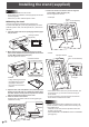
Installing the stand (supplied) Caution • Disconnect all cables from the monitor. • Firmly tighten the installation screws (supplied) with the hex wrench (supplied). • Ensure that you have sufficient space to work. 5. Fasten the stand to the monitor with the supplied screws (M4 x 10 with washers) (x4). Use the supplied hex wrench. • Landscape Screw (M4 x 10 with washers) nAttaching the stand Remove all packaging materials before starting work. To prevent the table (etc.
Installing the stand (supplied) nHeight/angle adjustment • Adjusting the height Adjust to a height that is easy to view. Approx. 5-29/32inch (15cm) TIPS • The height cannot be adjusted in a vertical installation. • Adjusting the angle Adjust to an angle that is easy to view. Approx.25° Approx.5° Approx.45° Approx.45° Caution • When moving the monitor, be sure to grasp only the frame. Grasping and applying pressure to the LCD panel may damage it. • Take care not to pinch your fingers.
Connecting Peripheral Equipment 1 2 3 4 5 6 Caution • Be sure to turn off the main power switch and disconnect the plug from the power outlet before connecting/ disconnecting cables. Also, read the manual of the equipment to be connected. • Be careful not to confuse the input terminal with the output terminal when connecting cables. Accidentally reversing cables connected to the input and output terminals may cause malfunctions and the other problems.
Connecting the Power Cord Caution • Use only the power cord and AC adapter supplied with the monitor. 1. Turn off the main power switch. 2. Connect the AC adapter (supplied) to the power cord (supplied). 3. Connect the AC adapter (supplied) to the AC input terminal. 4. Plug of the power cord (supplied) into the AC power outlet.
Binding Cables nFastening the cables The cables connected to the terminals on the rear of the monitor can be fastened with the cable clamp. Attach the cable clamps to the attachment parts on the back of the monitor and the stand, and bind the cables.
Turning Power On/Off Caution • Turn on the monitor first before turning on the PC or playback device. Turning power on/off Press the power button ( ) to turn the power ON/OFF. Power button ( ) Turning on the main power Power LED Power lamp status Main power switch Status of the monitor Green lit Power on Off Power off (Standby mode) Orange lit Input signal waiting mode Caution Caution • The main power must be turned on/off with the main power switch.
Basic Operation 6. [MENU/ENTER] button Displays and turns off the menu screen. (See page 18.) Settings can be entered when the menu screen is displayed. 1 7. [INPUT/RETURN] button The input selection menu is displayed. Press the [VOL+/ ]/[VOL-/ ] buttons to select the input mode, and press [INPUT/RETURN] button to enter.
Basic Operation nSwitching the screen size Even when the screen size is changed, the display may remain the same depending on the input signal. WIDE NORMAL Dot by Dot PC input Displays image so it fills the entire screen. AV input An image with a 4:3 aspect ratio is stretched to fill the entire screen. PC input Displays image so it fills the screen without changing the aspect ratio of the input signals.
Menu Items Displaying the menu screen TIPS Video adjustment and settings of various functions are enabled. This section describes how to use the menu items. See pages 19 to 21 for details of each menu items. • The menu will differ depending on the input mode. • The menu screen will close automatically if no operation is performed for about 15 seconds. nMenu screen display Caution 1 • Do not turn the main power switch off while the menu items are being displayed. Doing so may initialize the settings.
Menu Items Menu item details The menu will differ depending on the input mode. nPICTURE BRIGHT Adjusts the backlight brightness. CONTRAST Adjusts the difference between the bright and dark portions of the image. BLACK LEVEL Adjusts the entire brightness of the video signals. TINT Adjusts the hue. Selecting + changes the color towards green, and selecting - changes it towards magenta. COLORS Adjusts the color intensity. SHARPNESS Adjusts the sharpness of the image.
Menu Items nSETUP LANGUAGE Sets the display language for the menu screen. INPUT SELECT HDMI1/HDMI2 Select the input modes to be used for the PC/AV HDMI1 and HDMI2 input terminals. HDMI DUAL To use HDMI DUAL, select ON. AUDIO SELECT Selects the terminal used to input audio signals in each input mode. When HDMI DUAL is used, the HDMI1 settings are applied. AUDIO INPUT LEVEL Selects the maximum audio input level of the audio input terminal.
Menu Items nOTHERS SCREEN MOTION PATTERN Residual images are reduced by moving the screen. OFF.................. SCREEN MOTION function is disabled. PATTERN1 PATTERN2 PATTERN1....... A black screen spreads from the bottom of the screen and then shrinks to the bottom of the screen. If the monitor is installed in the portrait orientation, a black screen spreads from the left end of the screen and then shrinks to the left end of the screen. PATTERN2.......
Menu Items nDual screen display Two screens can be displayed by selecting PbyP mode. Set this function with “PbyP MODE” in the PbyP menu. PbyP Main screen Sub screen A main screen and a sub screen are displayed in a line. * The currently selected input signal is displayed on the main screen. * The following combinations are available for display: (Only when HDMI DUAL is set to OFF.
Initialization (Reset)/Functional Restriction Setting (FUNCTION) You can return the settings to their factory-preset values and restrict operations. 1. Hold down the [MENU/ENTER] button and [INPUT/ RETURN] button at the same time until “F” appears in the screen, and then press the [MENU/ENTER] button and [VOL-/ ] button at the same time while “F” appears.
Controlling the Monitor with a PC (RS-232C) You can control this monitor from a PC via RS-232C (COM port) on the PC. Communication procedure PC connection When a command is sent from the PC to the monitor, the monitor operates according to the received command and sends a response message to the PC.
Controlling the Monitor with a PC (RS-232C) nResponse code format When a command has been executed correctly O K Return code (0DH, 0AH) A response is returned after a command is executed. When a command has not been executed E R R nCommunication interval • After OK or ERR is returned, you must send the following commands. To set a timeout for the command response, specify 10 seconds or longer.
Controlling the Monitor with a PC (RS-232C) RS-232C command table How to read the command table Command: Command field (See page 24.) Direction: W When the “Parameter” is set in the parameter field (See page 24.), the command functions as described under “Control/Response Contents”. R The returned value indicated under “Reply” can be obtained by setting “????”, “ ?” or “???+” (repeater control) in the parameter field. (See page 24.) Parameter: Parameter field (See page 24.
Controlling the Monitor with a PC (RS-232C) PICTURE menu Function BRIGHT Parameter Reply Command Direction VLMP WR 0-31 Control/Response contents CONTRAST CONT WR 0-60 0-60 BLACK LEVEL BLVL WR 0-60 0-60 ○ TINT TINT WR 0-60 0-60 COLORS COLR WR 0-60 0-60 SHARPNESS SHRP WR 0-24 0-24 COLOR COLOR MODE ADJUSTMENT BMOD WR 0 0 STD 2 2 VIVID WHITE BALANCE THRU CTMP WR PRESET USER R-CONTRAST 3 3 sRGB (When the input mode is PC) 0 0 When the input mode is PC HDMI or D
Controlling the Monitor with a PC (RS-232C) SETUP menu Function LANGUAGE Command Direction LANG WR Parameter Reply 14 1 1 DEUTSCH 2 2 FRANÇAIS 3 3 ITALIANO 4 4 ESPAÑOL 5 5 РУССКИЙ 6 INPUT SELECT AUDIO SELECT HDMI1 HDSL Control/Response contents WR 0-1 * 14 ENGLISH ○ 6 0-1 0: PC HDMI, 1: AV HDMI HDMI2 H2SL WR 0-1 0-1 0: PC HDMI, 1: AV HDMI HDMI DUAL HDDU WR 0-1 0-1 0: OFF, 1: ON HDMI1 [PC] ASHP WR 0-1 0-1 0: HDMI, 1: STEREO MINI HDMI1 [AV] ASHA WR 0-1 0-1 0: HDMI,
Controlling the Monitor with a PC (RS-232C) Initialization/Functional Restriction Setting (FUNCTION) menu Command Direction ALL RESET Function RSET W Parameter Reply Control/Response contents ADJUSTMENT LOCK ALCK WR 0-2 0-2 0: OFF, 1:ON 1, 2:ON 2 OSD DISPLAY LOSD WR 0-2 0-2 0: ON 1, 1: OFF, 2: ON 2 LED OFLD WR 0-1 0-1 0: ON, 1: OFF TEMPERATURE ALERT TALT WR 0-2 0-2 0: OFF, 1: OSD & LED, 2: LED STATUS ALERT SALT WR 0-2 0-2 0: OFF, 1: OSD & LED, 2: LED 0 * ○ ○ ○ ○ ○ Others
Troubleshooting If you are experiencing any problem with your display, before calling for service, please review the following troubleshooting tips. There is no picture or sound. • Are the AC adapter and power cord properly connected? (See page 13.) • Is the main power switch off? (See page 15.) • Is the monitor in standby mode (power lamp is off)? (See page 15.) • Make sure correct input mode is selected. (See page 16.
Specifications nProduct Specifications Model LCD component Max. resolution (pixels) Max. colors Pixel pitch Viewing angle Screen active area inch (mm) Response speed Plug and play Power management Input terminals PC/AV PC Audio Serial (RS-232C) Output terminals Audio Speaker output Power requirement Operating temperature Operating humidity Power consumption (input signal waiting mode *1 / standby mode) Dimensions (excluding protrusions) inch (mm) Weight PN-K321 32" Class [31-35/64 inch (80.
Specifications nDimensional Drawings Note that the values shown are approximate values.
Specifications nCompatible signal timing (PC) Screen resolution VESA 640×480 800×600 848×480 1024×768 1152×864 1280×768 1280×800 1280×960 1280×1024 1360×768 1400×1050 1600×1200 1680×1050 1920×1200 3840×2160 Wide US TEXT *1 *2 *3 *4 *5 *6 4096×2160*2 1280×720 1920×1080 720×400 Vsync DisplayPort HDMI1 or HDMI2 60Hz 72Hz 75Hz 56Hz 60Hz 72Hz 75Hz 60Hz 60Hz 70Hz 75Hz 75Hz 60Hz 75Hz 60Hz 60Hz 60Hz 75Hz 60Hz 60Hz 60Hz 60Hz 60Hz 24Hz 25Hz 30Hz 50Hz 60Hz 24Hz 60Hz 60Hz 70Hz Yes Yes Yes Yes Yes Yes Yes Yes
Specifications nCompatible signal timing (AV) Screen resolution 1920 × 1080p 1920 × 1080i 1280 × 720p 720 × 576p 720 × 480p 640 × 480p(VGA) 720(1440) × 576i 720(1440) × 480i Frequency 24Hz 50Hz 59.94Hz 60Hz 50Hz 59.94Hz 60Hz 50Hz 59.94Hz 60Hz 50Hz 59.94Hz 60Hz 59.94Hz 60Hz 50Hz 59.94Hz 60Hz HDMI Yes Yes Yes Yes Yes Yes Yes Yes Yes Yes Yes Yes Yes Yes Yes Yes Yes Yes nPower management This monitor conforms to VESA DisplayPort power management.
Specifications nDisplayPort input (DisplayPort 20 pin) No. Function terminal pins nPC/AV (HDMI No. Function No. TM HDMI input terminal pins Connector) Function No. Function 1 MainLane 3- 11 Gnd 1 TMDS data 2+ 11 TMDS clock shield 2 Gnd 12 MainLane 0+ 2 TMDS data 2 shield 12 TMDS clock- 3 MainLane 3+ 13 Gnd 3 TMDS data 2- 13 CEC 4 MainLane 2- 14 Gnd 4 TMDS data 1+ 14 N.C.
Mounting Precautions (For SHARP dealers and service engineers) • When installing, removing or moving the monitor, ensure that this is carried out by at least 2 people. • Be sure to use a wall-mount bracket designed or designated for mounting the monitor. • This monitor is designed to be installed on a concrete wall or pillar. Reinforced work might be necessary for some materials such as plaster / thin plastic board / wood before starting installation.
PN-K321 Mu EN13A(1)