tirak ® XE301P Date: 06/28/05 Version:1 Service & Maintenance Manual for Electric Powered Hoists
BASIC TROUBLESHOOTING Repair and maintenance of the Tirak hoist should always be accomplished in a safe environment! WARNING The purpose of this sheet is for quick reference only. Most troubleshooting solutions can be found on pgs. 17 & 18 of the Tirak Instruction Manual included with each hoist.
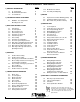
TABLE OF CONTENTS: TIRAK XE301P1 Page Page 1) GENERAL INFORMATION 1-1 1-2 1-3 UL Listing Card Model Identification Table Test Certificate 5-12 Modification Comment 5-13 Assembly and Adjusting 4 5 6 6) MOTOR 2) SECONDARY BRAKE ATTACHMENT 2-1 BSO500 - Secondary Brake Mounting Parts List 39 39 6-1 6-2 6-3 7 Replacement of Motor Winding (Stator) 40 Centrifugal Switch Replacement 42 Motor Parts List (E-3075 & E3076) 50 7) CONTROL BOX 3) WIRE ROPE DRIVING SYSTEM 3-1 3-2 3-3 3-4 3-5 3-6 3-7 3-8 3-9 3-1
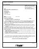
1) GENERAL INFORMATION 1-1 UL Listing Card Northbrook, Ilinois (847) 272- 8800 Melville, New York (631) 271-6200 Santa Clara, California (408) 985-2400 Research Triangle Park, North Carolina (919) 549-1400 Camas, Washington (360) 817-5500 TRACTEL INC GRIPHOIST DIV 110 SHAWMUT RD PO BOX 188 CANTON, MA 02021 TUFV Equiptment, Scaffolding April 18, 2002 TRACTEL INC GRIPHOIST DIV 110 SHAWMUT RD PO BOX 188, CANTON MA 02021 SA4785 Electric scaffold hoists, Models ETH-32L, XE301P, maximum load 700 lbs: Models
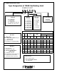
1-2 Model Identification Table Type Designation of TIRAK Scaffolding Hoist X SD 5 0 2 P X E 3 01 P 1 Tirak-type Wire Rope in. [mm] Capacity lbs.
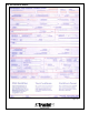
1-3 Test Certifacte XE301P Figure 103 6
2) SECONDARY BRAKE ATTACHMENT XE301P 2-1 BSO500 Secondary Brake Mounting Parts List # 1 2 3 4 5 6 7 Code 45735 9816 46847 67015 61645 20676 46496 Qty 1 4 1 1 1 2 4 Description Blocstop Pin Blocstop Washer Mounting Strap A Mounting Strap B Casing Pin Casing Washer Cotter Pin Dimensions / Comments 12 x 68 mm Ø 12 / Ø 19 x 1 mm (Qty. as needed) 163.5 mm w/lug (no bend) 163.5 mm 10 x 66 mm Ø 10 / Ø 16 x 1 mm (Qty.
3) WIRE ROPE DRIVING SYSTEM XE301P 3-1 Introduction NOTE Regular Inspection services will decrease downtime. Although the drive system of the Tirak hoist is one of the most simple and reliable system in the market, it still requires service from an authorized repair station for safe and efficient operation. It is recommended the following service procedures are performed every six (6) months but they may need to be repeated more often depending on the work environment the hoist is subjected to.
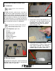
3-5 Casing Cover Removal 1) Remove the four (5) cap screw assemblies in the corners (Figure 305) consisting of the following: a. M6x50 socket head cap screws {Code #12016, Pos. 31} b. Lock-washers {Code #16616, Pos. 32} c. Flat washers {Code #36306, Pos. 71} d. Square nuts {Code #39356, Pos. 33} e. M6x16 socket head cap screw {Code #5336, Pos. 52} Figure 302 4) Inspect inside of cover {Code #63695, Pos.
3-6 Internal Inspection 1) Remove and inspect the stirrup adapter{Code #47867, Pos. 86} in Figure 310. Ensure it is straight and the anchor pin is secure. Figure 313 Figure 310 2) Remove and inspect the exit tube {Code #63725, Pos. 41} shown in Figure 311. Ensure it's free of debris inside. Replace as needed. Figure 311 4) Inspect the upper wire rope guiding plate {Code #63715, Pos. 46} and compare it to Figures 314 and 315. Figure 314 3) Remove the two socket head cap screws {Code #8926, Pos.
5) Remove the entrance tube {Code #40365, Pos. 49} and snap ring {Code #6846, Pos.57} as shown in Figure 320. Inspect the entrance tube and snap ring for damage. Ensure the entrance tube is free of debris. Clean or replace as necessary. Figure 322 8) Inspect the wire rope guiding band {Code #24187, Pos. 9} (Figure 323) for wear or damage. Replace as necessary (See Section 3-10). Figure 320 6) Inspect the wire rope guiding device {Code #63705, Pos. 47} in Figure 321. Replace as necessary.
10) Inspect the two roller pressure system {Code #23257 Pos. 80} shown in Figure 316. This inspection must be carried out every time the casing cover is removed. d) Be careful not to lose the two spring wahers {Code#16616 Pos. 32} and nyloc nuts {Code #7996 Pos.81}.(Figure 328). Perform the following check to determine if damage has occurred to the system: a) remove pressure system pin (Figure 325). Figure 328 e) Inspect the pressure system {Code #23257 Pos.
g) Inspect the rollers to ensure they roll freely and are not damaged. (Figure 331). 3-7 Reassembly 1) Re-grease the pressure system {Code #23257, Pos. 80} with wheel bearing or white lithium grease. WARNING DO NOT use molybdenum disulphide (moly-b) grease or graphite type grease! 2) Reinstall the lower guide plate {Code #40405, Pos. 48, Figure 322}, wire rope guiding device {Code #63705, Pos. 47, Figure 321} and upper guide plate {Code #63715, Pos. 46, Figure 312}.
2) Carefully place the casing cover over the pressure system dowel pin. Ensure it sits directly over the pin!!! (Figure 334). 7) Load test the hoist and check the Blocstop functions properly. NOTE General service of the wire rope drive system is now complete. If during the general service damage was discovered proceed as follows. WARNING It is prohibited to attempt repair of the pressure system. 3-9 Pressure System Replacement {Code #23257, Pos. 80} Figure 334 3) Place one hand on the casing cover.
3-10 Wire Rope Guide Band Replacement {Code #24187, Pos. 9} Though replacement is rare, it may be necessary if damaged beyond repair. This procedure requires that the drive sheave is removed. 1) Remove the oil drain plug as shown in Figure 336. Ensure that gearbox is lying with the oil plug to the high side to prevent excessive oil loss. This will allow air pressure to neutralize in the gearbox. 5) Remove the damaged wear band. Inspect and repair the casing base retaining lip as needed.
10) Press or use a rubber mallet to push the sheave into place. The air will expel from the oil plug. The sheave should move into position as air escapes (Figure 340). NOTE DO NOT stand in front of the oil plug hole as oil may spray. 11) Reinstall the oil plug and tighten. Figure 341 6) Reinstall the driver disc and remove excess air as in Section 3-10. 3-12 Driver Disc Bearing Replacement {Code #23836, Pos. 35} Though this is rarely required proceed as follows.
4) If replacement is necessary, using the correct gear puller remove the bad bearing as shown in Figure 343. Figure 343 5) Reinstall the new bearing and gently seat using a press. 6) Reinstall the driver disc. (Follow the procedure as outlined in Section 3-10) 7) Reinstall all drive components as in an outlined in Section 3-7. 8) Reinstall the casing cover per Section 3-8.
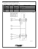
XE301P - 110V Spare Parts Position -2 4 9 10 16 23 24 27 28 31 32 33 34 35 36 39 41 42 46 47 48 49 51 52 53 57 68 69 70 71 72 77 79 80 81 83 85 86 87 87.1 87.2 87.3 87.4 87.5 100 100.1 102 Wire rope drive Part # 22048 63695 22357 24187 39516 40996 39306 39316 41996 39346 12016 16616 39356 40335 23836 39366 39376 63725 16286 63715 63705 40405 40365 4186 5336 8926 6846 37646 4176 37656 36306 41006 7146 16236 23257 7996 Qty.
Spare Parts XE301P - 110V Wire rope drive Drawing No Edition Date Page 27610 US-1 1/05 2/2
4) GEARBOX 2) Remove the casing cover and internal drive parts as shown in Figures 403, 404, 405, 406, 407, 408 and 409. 4-1 Required Tools (Figure 401) - 17 mm wrench or adjustable wrench Allen keys 8 mm, 5 mm internal and external snap ring pliers 2 pry bars 2 screwdrivers 1 gear puller 1 plastic or rubber mallet Brass punch Rags or towels Figure 403 Figure 401 2a) Remove all the casing cover screws {Code #12016 Pos. 31, & Code #5336 Pos.
2c) Remove the pressure spring {Code #23257, Pos. 80, refer to 27610, Section 3-13} as shown in Figure 406. 2f) Pry off the driver disc {Code #22357, Pos. 4, refer to 27610, Section 3-13} using 2 large screwdrivers as shown in Figure 409. Figure 406 Figure 409 2d) Remove the inlet tube {Code #40365, Pos. 49, refer to 27610, Section 3-13} as shown in Figure 407.
3) Using a 10 mm hex, remove the oil plug {Code #37646, Pos. 68} and drain the synthetic gear oil into a clean bucket. Inspect the oil for brass flakes or metal filings (Figure 412). 6) Rotate the gearbox cover {Code #40505, Pos. 3} slightly with a brass hammer (or soft hammer) and tap upwards as shown in Figure 415. Figure 415 7) Carefully pry off the gearbox cover {Code #40505, Pos. 3} as shown in Figure 416. Avoid damaging the casing base.
12) Remove any and all spacers {Code #25136, Pos. 21} as shown in Figure 421. 9) Remove the snap ring {Code #536, Pos 13} that sits on the input shaft (Figure 418). Figure 421 Figure 418 NOTE: There may be more than one spacer below the internal snap ring. 10) Remove the seal {Code #39306, Pos. 23, Figure 419}. The seal is destroyed during removal and must be replaced after reassembly of the gearbox. 13) Carefully turn the gearbox over and remove the cup seal {Code #39376, Pos.
15) Using a rubber dead blow mallet, hit the shaft pinion {Code #22367, Pos. 5} as shown in Figure 424. After several careful hits, the pinion gear assembly should come out through the front of the gearbox. 17a) If no press is available, carefully tap the worm gear assembly with a hammer or brass punch from the top of the base out the bottom of the base as shown in Figure 427. Figure 424 Figure 427 16) Inspect the pinion and bearing for any wear, damage, or discoloration (Figure 425).
20) Remove the steel worm {Code #22397, Pos. 7} through the large gearbox opening as shown in Figure 430. 4-2) Gearbox Reassembly 1) Install the top bearing {Code #37356, Pos. 20} on the steel worm gear and insert the assembly into the casing. With a brass hammer and punch, press the bearing into the gearbox as shown in Figure 432. Figure 430 NOTE: The bearing MUST be replaced in the same orientation. Failure to do so will cause the hoist to malfunction.
6) With a press or punch, seat the large brass gear {Code #22387, Pos. 6} into the gearbox as shown in Figure 437. Be careful not to damage worm wheel. Figure 434 4) Install the lower cup seal {Code #39376, Pos. 39} as shown in Figure 435. Figure 437 7) Install the spacer(s) {Code #25136, Pos. 21} and snap ring {Code #16576, Pos. 22} above the bearing as shown in Figures 438-440. Make sure that the snap ring is fitted into the groove.
8) Take the tool for inserting the top seal {Code #39306, Pos. 23} and place the seal on the tool as shown in Figure 441. Figure 444 10) Tighten the 4 screws {Code #4186, Pos. 69} and lockwashers {Code #16616, Pos. 72} as shown in Figure 445. Figure 441 8a) Hammer the seal {Code #39306, Pos. 23} into place as shown in Figure 442. Figure 445 11) Refill the gearbox with 1.4 liters of mineral oil per specification. Figure 442 9) Inspect the O-ring {Code #39286, Pos.
4-3 Emergency Controlled Descent Brake XE301P The controlled descent brake is found between the motor and gearbox. It is sealed and therefore should be clean and not worn. It only functions during intentional use for emergency descent. 4-4 Dissassembly an Checks of Emergency Controlled Descent Brake XE301P Figure 449 5) Examine the brake assembly. The shoes should not be worn and the springs should be correctly in place (See Figure 450). The lining should be secure.
4-6 Oil Level Gearbox WARNING USE MINERAL OIL ONLY! Hoist-Position for Oil Level Inspection Figure 452 Temperature Range: 14 to 122 °F -10 to +50 °C API Specification: SAE85W-140 GL5 Sample Oils: BP Hypogear EP 90 SHELL Spirax HD 90 TEXACO Multigear EP6 S80 W90 29
XE301P - 110V Spare Parts Position -1 3 5 6 7 8 9 10 11 12 13 14 15 16 18 19 20 21 22 23 301) 30.11) 30.21) 37 38 39 45 51 68 69 70 72 Part # 42707 41747 40505 22367 22387 22397 40305 24187 39516 40986 39286 536 25406 42016 40996 9996 39296 37356 25136 16576 39306 41066 41046 41056 576 37796 39376 21940 4176 37646 4186 37656 16616 Gearbox Qty. 1 1 1 1 1 1 1 1 1 1 1 1 1 1 1 1 1 1 1 1 1 2 1 2 1 1 1 1.
Spare Parts XE301P - 110V Gearbox Drawing No Edition Date Page E-3205 US-1 1/05 2/2
5) PRIMARY BRAKE FOR MOTOR WARNING Upon completion of any brake maintenance, it is mandatory that a load test of the hoist be completed! 5.1 Brake Type All Tirak XE301P hoists are fitted with the adjustable Precima type brake. This section covers the service and repair of this brake only. The XE301P has a 96V or 190V DC brake. Prior to maintenance, verify the brake voltage.
3) Measure the clearance (a) between the pressure plate and the black brake body with a feeler gauge. This should be done in all three places between the 3 fixing screws every 120 degrees (Figure 508). Figure 505 Figure 508 4) Measurement of the air gap (a) should be 0.012"(0. 3mm) (Figure 509 and Figure 510). If the air gap (a) needs an adjustment, refer to Section 5.6. Figure 506 2) Inspect the inside of the fan cover for excessive brake dust (Figure 507).
5.4 Brake Removal NOTE: Prior to removal, pay attention to the brake orientation and mark it for realignment (Figure 511). Figure 513 3) If the fan key {Code #16256, Pos. 23} is removable, do so. If not, just wrap some tape around the keyway for safety (Figure 514, 515). Figure 511 1) Remove the fan snap ring {Code #3866, Pos. 21} shown in Figure 512. Figure 514 Figure 515 4) Remove the three socket head fixing screws w/ locking washers.
NOTE: It is not necessary to unwire the brake. 6) Remove the brake rotor {Code #47416, Pos. 38} and inspect it (Refer to Section 5-6). Replace if worn or damaged (Figure 517). Figure 519 5.5 Reassembly Figure 517 7) Remove the snap ring {Code #3866, Pos. 21} and carefully pry the brake hub {#47426, Pos. 39} and key {Code #16256, Pos. 23} from the motor shaft as shown in Figure 518. Inspect the brake hub and replace if necessary.
4) Place the whole brake assembly {Code #49746 (110 V), or #47406 (220 V) Pos. 35} (Figure 516) over the motor shaft. 5) Using a 5mm allen wrench, screw the three socket head fixing screws w/ locking washers to hold the brake assembly in place. 6) Postition the fan key {Code #16256, Pos. 23} onto the motor shaft. Figure 521 7) Align the fan {Code # 16186, Pos. 7} key hole with the fan key {Code #16256, Pos. 23} and press downward.
3) Tighten down the three socket head fixing screws w/locking washers. 4) Measure the air gap as shown in Figure 524. If necessary, repeat steps 1-3 until an air gap of 0.012" (0.3mm) is achieved. Figure 526 2) Use a C-clamp to hold the brake assembly together as shown in Figure 527. Figure 524 5) Remove each of the three socket head fixing screws separately and apply a bead of silicone (Figure 525) to the tip to prevent water entry into the motor. Replace all three screws.
6) Install the brake onto the motor. Apply silicone to the brake end shield holes prior to installation to prevent water from entering the motor. Replace all three screws. 4) If there is any heat being generated, reinspect the brake air gap because the disc is most likely dragging. 5) If no heat is generated, reinstall the fan cover. When installing the fan cover, pull back as shown in Figure 532 to gain more clearance for the emergency descent lever.
5-12 Modification Comment Subject : Adjusting of the brake release lever. Reason : Simplify assembly and inspection The former instructions regarding the adjustment of the distance “b” (Figure 530) for the brake release lever “B” in (Figure 530) “with the brake opened” were based on an internal production instructions of the manufacturer by means of a special tool.
6) MOTOR 6-1 Replacement of Motor Winding (Stator) NOTE: The motor and control box must be removed before attempting to replace the motor winding (stator). 1) Remove the fan cover M5x10 hex screws {Code #16086, Pos. 31} as shown in Figure 601. Figure 603 4) Remove the whole brake assembly {Code #49746 (110 V), or #47406 (220 V) Pos. 35} by removing the three socket head fixing screws w/locking washers. (Figure 604). Figure 601 2) Remove the fan snap ring {Code #3866, Pos. 21} shown in Figure 602.
6) Remove the friction plate {Code #62026, Pos. 36} shown in Figure 606. Figure 609 8) Using a rubber mallet, drive out the motor shaft {Code #26587, Pos. 15} as shown in Figures 609 and 610. Figure 606 7) Remove the four M5x153 mm hex head screws {Code #26097, Pos. 12} holding onto brake flange shown in Figure 607. Figure 610 9) Remove the ring terminal winding wires (black-w, red-z, red-u and black-v) as shown in Figure 611.
10) Remove the small thermal protector wires from grey X1 and X2 (Figure 612). Figure 614 Figure 612 11) Remove the four socket head cap screws and lock washers that are holding the control box to the motor. Remove the control box (Figure 613). 6-2 Centrifugal Switch Replacement XE301P 1) Remove the motor and control box from the hoist (See Figure 615 on the next page). Remove the fan cover 4x8mm hex head screws {Code #16086, Pos. 31}. WARNING Discharge the start and run capacitors before proceeding.
3) Take off the primary brake {Code #49746 (110 V), or #47406 (220 V) Pos. 35} by removing the 3 socket head cap screws (See Figure 618). Figure 615 2) Remove the fan snap ring {Code # 3866, Pos. 21, Figure 616} and pry off the fan {Code #16186, Pos. 7} using 2 screwdrivers (See Figure 617). Make sure the screwdrivers are against the motor shaft when prying. Figure 618 4) Remove the brake disc {Code #47416, Pos. 38}, friction disc {Code #62026, Pos. 36}, snap ring {Code #3866, Pos.
6) Mark the position of the white centrifugal switch for easy alignment during reassembly as shown in Figure 621. 8) Unscrew the 3 M4x16 screws {Code #16996, Pos. 30} holding the centrifugal switch (See Figure 624). Figure 624 Figure 621 9) Mark the flange for reassembly (See Figure 625). 7) Loosen the 2 screws holding the centrifugal switch wires and remove the 2 spade connectors from beneath the screws (See Figures 622 and 623).
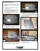
11) Remove the motor shaft assembly {Code #26587, Pos. 15, Figure 627}. 13) Remove the ball bearing 6004-RS1 {Code #16536, Pos. 18} by removing the snap ring {Code #536, Pos. 20, Figure 630} and pulling with a bearing puller (See Figures 631 and 632). Figure 627 12) Loosen the set of screws holding the mechanical part of the centrifugal switch (See Figure 628) and push the assembly away from the ball bearing to allow room for a puller (See Figure Figure 629).
14) Remove the bearing. Notice that one side is sealed and the other side is not (See Figure 633). Figure 633 17) Remove the white centrifugal switch and mechanical actuating mechanism (See Figure 636 and 637). Figure 636 15) Remove the snap ring {Code #536, Pos. 20} in Figure 634. Figure 637 NOTE We suggest you layout the parts on the workbench for ease of reassembly (See Figure 638). Figure 634 16) Remove the bearing cover {Code #27935, Pos. 6} in Figure 635.
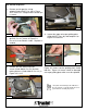
18) Check the centrifugal switch contacts for burn, malfunction, etc. Manipulate the switch to see if the contacts open and close (See Figure 639). Figure 642 Figure 639 19a) If it stays open, clean the contacts with contact cleaner and emery cloth (See Figure 643 and 644). NOTE Sometimes contact cleaner and emery cloth can repair a malfunctioning switch (See Figure 640). Figure 643 Figure 640 19) Before installation of a new switch, check that it functions properly with a meter.
21) Replace the bearing cover {Code #27935, Pos. 6, Figure 637} and reaffix the snap ring {Code #536, Pos. 20, Figure 636}. Repack the ball bearing with grease. Note that the seal is on the bottom and the bearing is open to the top (See Figure 646). 23) Replace the snap ring {Code #536, Pos 20} on the shaft (See Figure 630). Sqeeze the mechanical portion of the centrifugal switch while sliding it up the shaft (See Figure 651). With the set screw lock it into position on the shaft (See Figure 628).
26) Put the cast aluminum brake end shield on the motor shaft (See Figure 652). Figure 652 27) Realign the switch and retighten the 3 M4x16 screws {Code #16996, Pos. 30, Figure 629}. Place silicone around the bottom of the cast aluminum end shield to seal the joint between the winding and shield. 28) Place the motor shaft assembly into the winding, align the marks and tighten the 4 M5x153 {Code #26097, Pos. 12} bolts. 29) Reassemble the brake per Section 5-12. 30) Replace the fan cover.
XE301P - 110V Spare Parts Position 1 5 6 7 8 (8a*) (8b*) 10 12 14 15 18 19 20 21 22 23 (25*) (26*) (27*) (28*) 30 31 33 35 36 37 38 39 40 Part # 15648 26597 26107 27935 16186 26607 47837 69536 41996 26097 15796 26587 16536 26376 536 3866 39316 16256 16206 16236 16706 3776 16996 16086 16246 49746 62026 62446 47416 47426 61716 110V / 1ph. 0.55 kW / 60Hz Motor type: UBE 80/11-4F-100V Qty.
XE301P - 220V/1ph. Spare Parts Position 1 5 6 7 8 (8a*) (8b*) 10 12 14 15 18 19 20 21 22 23 (25*) (26*) (27*) (28*) 30 31 33 35 36 37 38 39 40 Part # 15638 26577 26107 27935 16186 26607 47847 69536 41996 26097 15796 26587 16536 26376 536 3866 39316 16256 16206 16236 16706 3776 16996 16086 16246 47406 62026 62016 47416 47426 61716 220V / 1ph. 0.55 kW / 60Hz Motor type: UBE 80/11-4F-200V Qty.
7) CONTROL BOX XE301P NOTE: All of the following checks are done without power to the motor or hoist. 7-1 Tools Required - Volt/Ohm meter (left in Figure 701) - Digital Capacitor meter (up to 275uF) - 2 insulated screwdrivers Figure 703 3) Check that the protective cover around the emergency stop button is in good condition and is not loose. Replace it if necessary. The 3 screws must be tightened and have silicone applied to seal against water entry.
The two shorter prongs should not show continuity (Figure 706). 3) A full size diagram should be folded and tucked in place next to the relays. Check that the full size diagram matches the tag (Figure Figure 706 NOTE: If either of the shorter prongs show continuity to ground, a short circuit has occurred and must be fixed. It is possible that the plug is wired incorrectly or the insulation is cut. Open the plug and investigate. Also check the cord grip. Figure 709 709).
4) Check that the run winding is not shorted to ground. There should be no continuity between U or V and the control box casing (Figure 714). If the connection is shorted, the stator must be replaced. Figure 714 Figure 711 2) Check that the starting winding is not shorted to ground. There should be no continuity between W or Z and the control box casing (Figure 712). If the connection is shorted, the stator must be replaced. 7-6 Fuse Check, F1 {Code #22366 (110V), Pos. 11, Code #21076 (220V), Pos.
3) The UP relay, K1, coil resistance should be approximately 310 ohms. Place the ohmmeter test probes on the A1 and A2 screws of the K3 relay. Check the resistance (Figure 719, shows 305 ohms, OK). If the connection is open or shorted, replace the UP/DOWN double relay {Code #60456 (110 V), #60466 (220 V) Pos. 8}. Figure 716 7-8 Relay Coil Resistance, K1, K2, K3 1) Main relay K3 coil resistance should be approximately 310 ohms. Place the ohmmeter test probes on the A1 and A2 screws of the K3 relay.
Figure 721 Figure 723 2) With a digital capacitor tester, measure the start and run capacitance by placing the test clips on position 4 and position 6 of the terminal board M1 (Figure 722, shows 277uf, OK). This number is the combination of the start capacitor CA(180uF) + run capacitor(s) CB(35uF) = 250uF +/- 10%. If the total is outside this range, check each capacitor as follows.
7-11 Centrifugal Switch Check With an ohmmeter, place the the probes on position 5 and 6 of the terminal board M1 (Figure 725 on the next page). The switch should be closed when the motor is not running. When the motor runs, the motor draws high amps and the switch opens. If it stays closed, it is stuck and the switch should be repaired or replaced. 7-12 Pushbutton Checks 1) Contacts are marked NO = “Normally Open“ or NC = “Normally Closed”. Figure 726 shows continuity for a NC contact.
7-15 Power Check WARNING The following checks are performed with power to the hoist motor. Whenever power is applied to the hoist, use extreme caution especially with the control box open as part are energized. Only trained and qualified personnel should service the hoist to avoid injury or death. 1) Open the emergency stop by twisting the red knob. It should spring open. This should cause the main relay, K3, to energize.
XE301P - 110V- Direct Spare Parts Position 1 2 3 4 6 7 8 9 10 11 12 13 14 15 17 18 19 21 22 23 24 25a 25b 27 28 29 30 31 32 33 (34*) (35*) 37 38 40 41 43 44 46 47 48 Part # 26647 47917 17846 65115 22905 35435 60406 60456 22426 10917 22366 21076 40796 24346 18566 22856 21706 21716 21746 18296 37776 103 2311 6031 15026 18276 18256 25056 19196 23686 18906 10991 11021 33156 17016 33126 16 7536 16246 456 44466 44476 110V / 1ph. / 60Hz GG 13/10.14 Qty.
Spare Parts XE301P - 110V- Direct 110V / 1ph. / 60Hz GG 13/10.
XE301P - 220V/1ph. - Direct Spare Parts Position 1 3 4 5 6 7 8 9 10 12 13 14 15 16 17 18 19 21 22 23 24 25a 25b 27 28 29 30 31 32 33 (34*) (35*) 36 37 38 39 40 41 43 44 45 46 47 48 Part # 26637 42757 17846 43285 35805 35435 60356 60466 22426 10917 22366 21076 24346 18566 40796 22856 21706 21716 21746 18296 37776 103 2421 6031 15026 18256 23926 25056 38546 42766 18906 10991 11021 18276 33156 17016 10236 33126 7536 16616 16246 456 23616 44466 44476 220V / 1ph. / 60Hz GG 13/10.3 Qty.
Spare Parts XE301P - 220V/1ph. - Direct 220V / 1ph. / 60Hz GG 13/10.
8-5 Wiring Connection of Stator XE301P Figure 801 71
9) WIRE ROPE SPECIFICATION TIRAK There seems to be some question as to selection of wire rope due to the many people offering wire rope today Before Tractel chooses a supplier of wire rope we run an endurance test or cycle test to make certain that the rope functions well in the hoist and has good life. The European norms require 1000 cycles minimum, UL testing requires 500 cycles. We require 2000 cycles and test with a high-speed hoist 60 ft./ min.
9-1 Wire Rope Specifications - XE301P (Page 2 of 2) NOTE: As of 2/15/2002, 5/16” diameter should be used (as taken from various product literature).
9-2 Labels and Nameplates 74
9-3 Checklist NOTE: Completion of the checklist MUST always be done before operating the hoist.
9-4 Hoist Specification LE501P1 5x19 or 5x26 with fiber core lubricated, Wire rope classification/construction preformed IPS or XIPS in. 5/16 in. mm 8.4 mm in. 0.319 to 0.331 mm 8.1 to 8.4 lbs 10,000 kN 44.5 nominal diameter maximum allowed diameter tolerances minimum actual breaking strength Table 1003 Figure 1001 Hoist Model XE301P with BLOCSTOP model BSO 500 lbs 700.0 kg 300.0 ft/min 35.0 Rated Load Lifting Speed m/min 11.0 lbs 77.0 kg 35.
TRACTEL Inc GRIPHOIST Division 110, Shawmut Road Canton, MA 02021 Tel: 800-421-0246 Fax: 781-828 3642 griphoist.usa@tractel.com TRACTEL LTD GRIPHOIST Division 11020 Mirabeau St Anjou QUEBEC, H1J 2S3 Tel. +1 (514) 493 3332 Fax. +1 (514) 493 3342 griphoist.canada@tractel.com © Copyright - All rights reserved 77 TRACTEL Inc GRIPHOIST Division Branch Office: 315 Cloverleaf Dr. Building E Baldwin Park CA 91706 Tel. +1 (626) 937 6727 Fax.