
Specifications

Driver-Controlled Main Differential Lock
86 MAINTENANCE MANUAL
Hazard Alert Messages
Read and observe all Warning and Caution
hazard alert messages in this publication. They
provide information that can help prevent seri-
ouspersonalinjury,damagetocomponents,or
both.
WARNING
Topreventseriouseyeinjury,alwayswear
safe eye protection when you perform vehi-
cle maintenance or service.
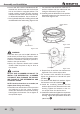
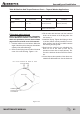
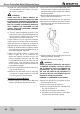
Description
Some Meritor drive axle models have a driver-
controlled main differential lock (DCDL). This
differential lock is operated by a differential
mounted, air actuated shift unit. When activat-
ed, the shift unit moves a sliding collar which is
installed on the splines of the axle shaft. When
engaged, the collar locks the axle shaft to a
second set of splines on the differential case.
Both driven wheels are then simultaneously en-
gaged. Figure 6.1.
NOTE:
Meritor differential models with driver-con-
trolled differential lock equipment are manu-
factured in metric dimensions and sizes.
When these differential are serviced, it is im-
portant to use the correct metric size tools on
the fasteners. See the Section 8.
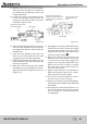
Removal Differential Differential from
the Axle Housing
Before the differential can be removed or in-
stalled, the differential lock must be shifted
into and held in the locked or engaged posi-
tion. The locked position gives enough clear-
ance between the shift collar and the axle
housing to permit the removal or installation
of the differential.
NOTE:
If the axle shafts were removed for or towing
with the differential in the unlocked or dis-
engaged position, Install the left hand axle
shaft into the housing before continuing.
Perform the following steps for reinstalling
the axle shafts into the axle housing.
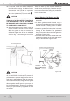
1. Remove the protective covers, if used, from
the wheel hubs.
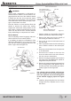
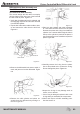
2. If the drive axles are equipped with a main
differential lock, shift the differential to the
unlocked or disengaged position. Install the
axle shafts with two sets of splines and new
gaskets in the correct location as follows. Fig-
ure 5.109.
A. Push the axle shaft and gasket into the hub
and housing until the shaft stops against the
differential lock collar.
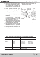
B. Pushdownandinontheaxleshaftange
and rotate the shaft until the splines of the
shaft and the shift collar are engaged.
C. Push the axle shaft further into the housing
until the shaft stops against the differential
side gear.
D. Pushdownontheaxleshaftangeandro-
tate the shaft until the splines of the shaft
and the side gear are engaged.
E. Push the axle shaft completely into the
housinguntiltheaxleshaftangeandgas-
ketareushagainstthewheelhub.
SHIFT COLLAR
PISTON
CYLINDER
SHIFT PORK
SENSOR
SPRING
SHIFT SHAFT
O-RING
CAPSCREW MANU-
AL ENGAGING
Figure 6.1