
Specifications

89
Driver-Controlled Main Differential Lock
MAINTENANCE MANUAL
Differential and Gear Assembly and
Main Differential Lock
Threaded DCDL Shift Assembly
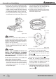
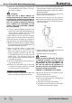
The current design shift fork does not employ
roll pins. Nubs on the inner face of the fork hold
the shift collar in place. Figure 6.4.
1. Verify that the differential lock is released and
the engaging capscrew and seal are removed
from the shift cylinder.
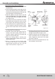
2. Tap the shift collar with a rubber mallet to loos-
en and remove the collar from the shift fork.
Figure 6.5.
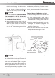
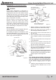
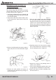
5. Place the shift cylinder and piston assembly
inavisethathasbrasscoversoverthejaws.
Remove the piston and O-ring from inside the
cylinder. Use a narrow drift through the hole in
the top of the cylinder to push out the piston. It
may be necessary to use a mallet to tap out the
piston. Figure 6.8.
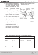
6. Carefully remove the O-ring from the piston.
Use a thin pointed tool to remove the O-ring.
Do not damage the piston. Figure 6.9.
7.Inspect the O-ring for any damage such as
cracks, cuts or breaks.
• IftheO-ringisdamaged,replaceitwithanew
O-ring when you assemble the components.
8.Clean and inspect all shift assembly parts.
See the Section 4.
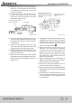
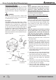
3. Remove the differential lock sensor switch, if
used,andjamnutfromthedifferential.Figure
6.6.
4. Remove the shift cylinder and piston as-
sembly from the differential by turning it to
the left. Figure 6.7.
Figure 6.6
Figure 6.5
SHIFT FORK
SHIFT COLLAR
Figure 6.7
Figure 6.8
DRIFT
Figure 6.9