
Specifications
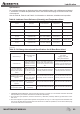

Driver-Controlled Main Differential Lock
90 MAINTENANCE MANUAL
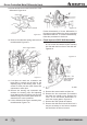
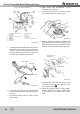
9. Pull the shift shaft from the fork and out of the
differential. Figure 6.10.
10. Remove the shift shaft spring and fork from
the differential. Figure 6.11.
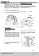
11. If roll pins are used, use a hammer and
brass drift to remove the roll pins for the
adjustingringsonthebearingcaps.Ifcap-
screws or cotter pins are used, remove the
capscrews or cotter pins.
12. Remove the bearing cap capscrews and
washers, the bearing caps and adjusting
rings. Match mark one bearing cap and one
differential leg so that these parts will be as-
sembled in the correct positions..
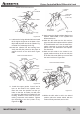
13. Lift the differential and gear assembly from
the differential. Figure 6.12.
Further disassembly of these differentials is
the same as axles without the driver-controlled
main differential lock. To continue disassembly,
follow the procedures in Section 3.
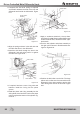
Fixed capscrew DCDL Shift Assembly
1. To remove the differential lock sliding shift col-
lar, tap out the two retainer roll pins until they
are level with the inner face of the shift fork.
Figure 6.13.
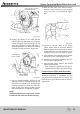
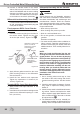
2. If required, remove the differential lock shift
unit.
A. Removethesensorswitchandjamnut.
B. Remove the four capscrews and washers
that hold the cylinder cover. Remove the
cover. On the 160 Series differentials, re-
move the copper gasket. Figure 6.14.
C. Remove the shift cylinder and piston.
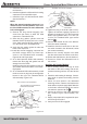
D. Remove the shift shaft from the shift fork. It
may be necessary to use heat to separate
the shaft from the fork to loosen it.
SHIFT FORK
FORK
DCDL CASTING
Figure 6.10
FORK
SHIFT SHAFT SPRING
Figure 6.11
Figure 6.12
ROLL PINS — TAP
UNTIL EVEN WITH
INNER FACE OF
SHIFT FORK
Figure 6.13