
User manual


10
User manual
ENG
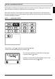
STEP 2 - HYDRAULIC SCHEME SETUP
Select a hydraulic scheme for controller operation.
Move between schemes with buttons
and .
.
selection with the
button.
In case you choose the wrong scheme, return to
scheme selection with the
button.
Later you can change the selected hydraulic scheme with service parameter
S1.1.
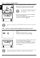
STEP 3 - SETUP OF HEATING CURVE STEEPNESS FOR THE FIRST CIRCUIT
circuit.
Change the value with buttons
and .
.
-
ing curve steepness with the
button.
In case you choose the wrong heating curve steep-
ness, return to heating curve steepness selection
with the
button.
Later you can change the heating curve steepness with parameter P2.1. The
meaning of heating curve steepness is detaily described on page 36.
All schemes with mixing heating circuit
wall heating.