Split Type Inverter Room Air Conditioner OPERATION MANUAL MODELS AY-X24MCJ AE-X24MCJ Thank you for selecting SHARP air-conditioner. Please read this manual carefully before operation and keep it for further reference.
and cleaning ing ing Specifications NOTE:All the pictures in this manual are just schematic diagrams. The actual product is the standard. that should be prevented. that Collection of such waste should be separated for special treatment as required by local regulations.
1.
, pl ease ref er the mat ter to a qualified air conditioner contractor. objects Don’t expose yoursel f to col d output air for prolonged periods as it may affect your physical condition. To change the airflow direction, adjust the vertical and lateral air flow direction by using the remote control. Don’t expose animals and plants directly to the output air flow as it may have a detrimental effect on them. This air conditioner is designed for normal residential use.
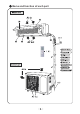
Air conditioners absorb heat in the room and transmits it to the outdoor unit, so that indoor ambient temperatures are decreased. Its cooling capacity will increase or decrease according to outdoor ambient temperature. If the unit is running in COOL mode and in low ambient temperature, frost may be formed on the heat exchanger. When indoor heater exchanger temperature decreases below zero, the indoor unit microcomputer will stop the compressor running to protect the unit.
Na me and function of each part X-FAN
Note: Be sure that there are no obstructions between receiver and remote control; Don't drop or throw the remote control; Don't spill any liquid on the remote control; Don't leave remote control directly in sunlight or hot environments. Pres s this button to turn Sleep mode on or off. Sleep mode "off" is defau lt when switched on. Sleep functi on is cancelled when unit is switched off. Sleep mode durati on can be adjusted . Sleep mode is not avail able under Fan and Auto modes.
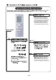
Name and function of wireless remote control Some buttons on this control are not applicable to this unit. Preset temperature is increased by pressing this button. Continuously pressing and holding for 2 seconds changes the temperature rapidly. ON/ OFF X-FAN X-FAN Preset temperature is decreased by pressing this button. Continuously pressing and holding for 2 seconds changes the temperature rapidly. The temperature adjustment is unavailable under the Auto Mode.
Some buttons on this control are not applicable to this unit. ON/ OFF Press this button to select Timer On setting. Pressing the + or - button during the first 5 seconds adjusts the time value by one minute each time pressed. Holding the + or - button down for more than 2 seconds changes the time rapidly. While time is blinking, press Timer On button to confirm setting. After setting, repressing the Timer On button cancels the operation.
Press On /Off button to start or stop operation. ON/ OFF ON/ OFF to switch On or Off the display on the main unit. m odels to switch X-FAN the fan will con tinue to x-fan after the unit is stopped to remove X-FAN X-FAN X-FAN the X-FAN function is not operated. senses the room temperature automatically to select a suitable running method for room comfort.
To set the guide louvre to a desired position, press Swing Up and Down button continuously for more than 2 seconds and hold until desired position is achieved. Releasing the button now stops the swinging at the desired position. After Swing Up and Down mode is switched on, pressing the button again within 2 seconds circulates between the various settings. If button is pressed more than 2 seconds later, the function is switched off.
on the main unit. Operation will be in Auto Run mode and the temperature setting or fan speed cannot be changed. To operate: Press the AUTO/STOP button and the unit will enter into AUTO RUN mode. The microcomputer will monitor the room temperature to select the (COOL, HEAT, FAN) mode automatically, to obtain the comfortable effect. To turn off: Press the AUTO/STOP button to switch the unit off.
Care and Cleaning to prevent at the circuit breaker the risk of electric shock. pour or spray liquids directly onto the indoor or outdoor units for cleaning, to prevent risk of electric shock. Only wipe the Rotate the front panel upwards in the direction of the arrow. While holding both sides of the front panel, remove by pulling forwards. Some minor force may be required. Before cleaning, remove the LCD display (if fitted) from the front panel.
Care and Cleaning Removing Rotate the front panel upwards in the direction of the arrow. Pull the air filter downwards and remove from the unit. water temperature should be and leave to dry naturally in a shady location. Never dry it with a heater or open flame, as fire or deformation may occur. in the di rec tion of the ar rows, then cl os e the front panel. Never operate the unit if the wiring or connections have been damaged. report to a licenced contractor.
The air conditioner is not user serviceable. if attempt to If a bad smell has been accumulated from the environment, clean the air filter. If smells persist, contact your Approved Service Centre to arrange cleaning. fluid gurgling noises. This is not a fault - it is the sound of flowi ng refrigerant.
will Has the circuit breaker device tripped off? Have the wiring or connections been damaged?Please report to an authorised air conditioner contractor. Is the fan other working Check that there is no magnetic or electrical interference near the main unit that may be affecting the operation of the controller. Is the wireless remote control within its operating range, or obstructed? Check the condition of the batteries and replace if necessary. Check if the wireless remote control is damaged.
air flow is stopped fros t can be for med on the outdoor heat exchanger. The unit will automatically defrost and the indoor unit will stop blowing air for 3-12 mins. During defrost operation, water or vapour may be emitted. ,disconnect from the power supply, and report to an authorised air conditioner contractor in the following situations. St rong odours are emi tted Circuit breaker continuously trips off. Water has dripped into or been splashed onto the unit.
The unit must only be installed by authorised air conditioner contractors according to municipal or government regulations and in compliance wi th this manual. The unit should be installed with a dedicated electrical circuit, and a circuit breaker should be fitted in accordance with regulations. Proper installation position is vital for correct and efficient operation. Avoid the following positions: liquids electro-magnetic Where salt-laden air is a problem (such as close to coastal areas).
A dedicated power supply circuit should be used, in accordance with local electrical safety regulations. The product should be installed by a licenced air conditioning contractor in accordance with AS/NZS3000 and your electrical supplier's rules. A circuit breaker should be installed. WARNING: inadequate or incorrect electrical connections may cause electrocution or fire. . P lease ensure the the unit is reliably earthed. the air conditioner is the earthing wire, and cannot be used for any other purpose.
Installation dimension diagram Installation dimension diagram Space to the ceiling 15 cm Above 15cm Above 15cm Above Space to the wall Space to the wall 300 cm 230 2 cm Above Above Air outlet side Air inlet side 30 cm Ab ov e Space to the obstruction 50cm Above Space to the floor 30cm Above mA bo ve 50cm Above 20 0c Space to the wall Air outlet side 18
Installing the indoor unit , and leveled to ensure correct drainage. Wall Mark on the middle of it Wall Gradienter Space to the wall 150mm above Space to the wall 150mm above Left (Rear piping hole) Fig.1 Right (Rear piping hole) proper Drainage hoses passing through indoor areas should be wrapped with insulation material. by rotating upwards. Remove the electrical connection cover plate and screw. hole in the provided using Replace .
Installing the indoor unit All interconnecting wiring between indoor and outdoor unit must be performed by a licenced electrical contractor in accordance with AS/NZS3000. the unit to screws adequately to prevent loosening. Ensure the electrical connections are properly earthed to prevent electrical shocks. Ensure all wiring connections are secure and the cover plates are reinstalled properly. Poor installations that allow dust or moisture incursion may cause fire or electrocution.
Installing the Outdoor Unit Remove electrical connection access plate (either right hand side or front) from the outdoor unit. Replace access plate (either right hand side or front) on the outdoor unit. Incorrect unit failure.
Installing the Outdoor Unit soapy gas detection are leaking. Outdoor attach satisfactorily.
satisfactory to the product. product. Are the inlet and outlet air openings blocked? Is the quantity of gas charge sufficient for the length of pipe run? may be insufficient.
Specifications Model AY-X24MCJ;AE-X24MCJ Function COOLING HEATING Rated Voltage 220-240 Rated Frequency 50Hz Total Capacity (W) (High/Standard/Low) Total Capacity (Btu/h) (High/ Standard/Low) 7200/6500/2250(W) 9000/7200/1800(W) 24550/22200/7700(Btu/h) 30700/24550/6150(Btu/h) 2600/2000/550 3100/1990/500 2600/2000 3110/1990 11.3/8.7 13.5/8.
AE-X24MCJ Model of Outdoor Unit Compressor Manufacturer/trademark Compressor Model C-6RZ146H1A Compressor Type Double Rotary L.R.A. (A) 41 Compressor RLA(A) 8.4 Compressor Power Input(W) 1640 Overload Protector 1NT11L-3979 Throttling Method Capillary throttling Starting Method Transducer starting Working Temp Range (℃) -15℃≤T≤46℃ Condenser Aluminum fin-copper tube Rows-Fin Gap(mm) 2-1.
:$55$17< $LU &RQGLWLRQHUV 6KDUS &RUSRUDWLRQ RI $XVWUDOLD 3W\ /WG JXDUDQWHHV WKDW VKRXOG D GHIHFW LQ WKLV SURGXFW GXH WR HLWKHU )$8/7< 0$7(5,$/6 RU :25.
SHARP FOR LOCATION ENQUIRIES WITHIN AUSTRALIA REGARDING YOUR LOCAL SHARP APPROVED SERVICE CENTRE VISIT OUR WEBSITE AT www.sharp.net.au OR CALL SHARP CUSTOMER CARE 1300 135 022 (LOCAL CALL COST APPLY WITHIN AUSTRALIA) SHARP CORPORATION OF AUSTRALIA PTY LTD SHARP FOR LOCATION ENQUIRIES WITHIN NEW ZEALAND REGARDING YOUR LOCAL SHARP APPROVED SERVICE CENTRE VISIT OUR WEBSITE AT www.sharp.net.
SHARP CORPORATION OF AUSTRALIA PTY LTD ABN 40 003 039 405 1 Huntingwood Drive HUNTINGWOOD NSW 2148 www.sharp.net.