
Service manual
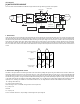
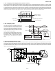
Table Of Contents
- TopPage
- SPECIFICATIONS
- EXPLANATION OF CIRCUIT AND OPERATION
- [1] BLOCK DIAGARM
- [2] FUNCTIONS
- 1. FREQUENCY CONTROL
- 2. OVER CURRENT PROTECTION
- 3. COMPRESSOR PROTECTION CONTROL
- 4. POWER TRANSISTOR MODULE PROTECTION
- 5. SERIAL SIGNALS
- 6. THERMISTOR OPEN OR SHORT
- 7. MISWIRING CHECK
- 8. SAFETY TIME
- 9. PUMP DOWN SWITCH
- 10. CONTROL OF COMPRESSOR OR AND EXPANSION VALVE
- 11. DEFROST OPERATION
- 12. Power factor module Output voltage
- [3] ACTIVE FILTER CIRCUIT
- [4] EXPLANATION OF IPM DRIVE CIRCUIT
- FUNCTION AND OPERATION OF PROTECTIVE PROCEDURES
- REFRIGERATION CYCLE
- DISASSEMBLING PROCEDURE
- PartsGuide
- EndPage
AEX3M18JR
2 – 6
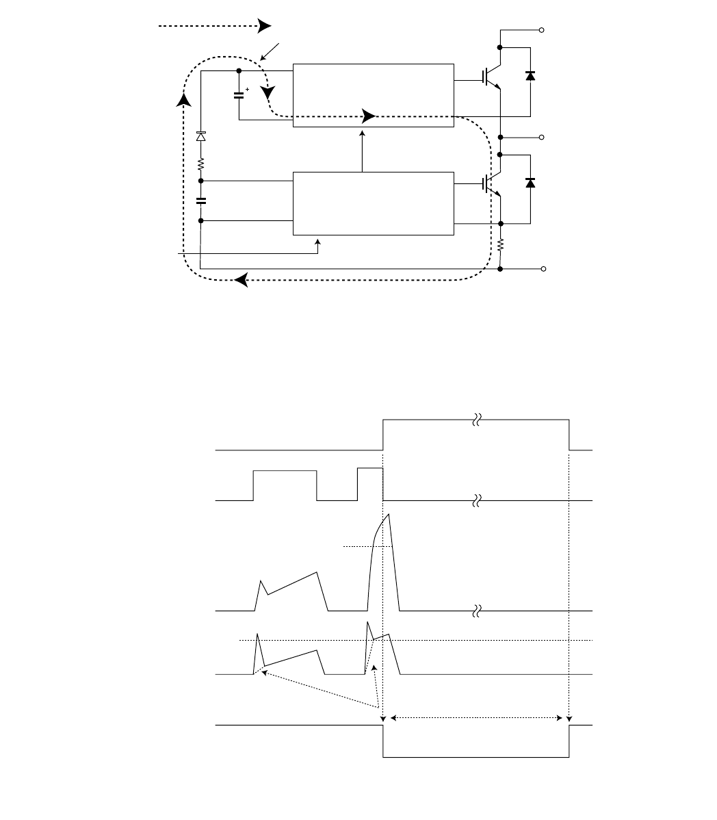
[4] EXPLANATION OF IPM DRIVE CIRCUIT
The power supply for the IPM drive, and the shunt resistor for over current detection, etc., are provided out of the IPM (in control PWB).
1. IPM drive power supply circuit
The power supply for driving the upper-phase IGBT (HU, HV, HW) drive employs a Bootstrap system.
The 15-V power supply for the lower-phase IC is provided by the control printed circuit board (PWB).
1. Brief explanation of Bootstrap system (single power drive system)
To supply power to the upper-phase IC, the microcomputer (IC1) turns ON the lower-phase IGBT (LU, LV, LW).
It results in a charging current that flows through the electrolytic capacitor in each upper-phase IC input and charges the Bootstrap capacitor up to
15V voltage.
The power supply for the subsequent stages is stored when the lower-phase IGBT is ON in common drive control of the compressor.
2. DC over current detection circuit
When a current about 24A or higher flows through the shunt resistor (R100) on IPM printed circuit board (PWB), the voltage on this resistor is input to
IPM CIN pin (16). Then, the gate voltage of the lower-phase IGBT (LU, LV, LW) inside the IPM turns OFF to cut the over current off. At the same time,
an L output which lasts about 1.8 ms is generated from IPM Fo pin (18), and it results in an L level input to over current detection input pin (53) of the
microcomputer (IC1) and then turns OFF the compressor driving signal output (IC1 from pins (65) to (70)) to the IGBT gate.
P(Vcc)
U,V,W,
V
D
V
DB
V
CIN
(
n
)
N-side
IGBT
N(GND)
Bootstrap capacitor
High-voltage-withstanding,
high-speed recovery diode
LVIC
(LU,LV,LW)
HVIC
(HU,HV,HW)
Bootstrap circuit
Initial charge period
Charging current group
SET
RESET
About 24A
SC
SC reference voltage
Delay by CR time constant circuit
About 1.8 ms
a1
Protection circuit status
Output current Ic (A)
Sense voltage relative
to shunt resistance
Error output Fo
(Lower phase)
Internal IGBT gate