
Service manual
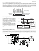
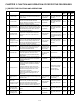
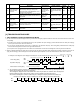
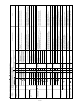
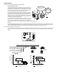
Table Of Contents
- TopPage
- SPECIFICATIONS
- EXPLANATION OF CIRCUIT AND OPERATION
- [1] BLOCK DIAGARM
- [2] FUNCTIONS
- 1. FREQUENCY CONTROL
- 2. OVER CURRENT PROTECTION
- 3. COMPRESSOR PROTECTION CONTROL
- 4. POWER TRANSISTOR MODULE PROTECTION
- 5. SERIAL SIGNALS
- 6. THERMISTOR OPEN OR SHORT
- 7. MISWIRING CHECK
- 8. SAFETY TIME
- 9. PUMP DOWN SWITCH
- 10. CONTROL OF COMPRESSOR OR AND EXPANSION VALVE
- 11. DEFROST OPERATION
- 12. Power factor module Output voltage
- [3] ACTIVE FILTER CIRCUIT
- [4] EXPLANATION OF IPM DRIVE CIRCUIT
- FUNCTION AND OPERATION OF PROTECTIVE PROCEDURES
- REFRIGERATION CYCLE
- DISASSEMBLING PROCEDURE
- PartsGuide
- EndPage
3 – 4
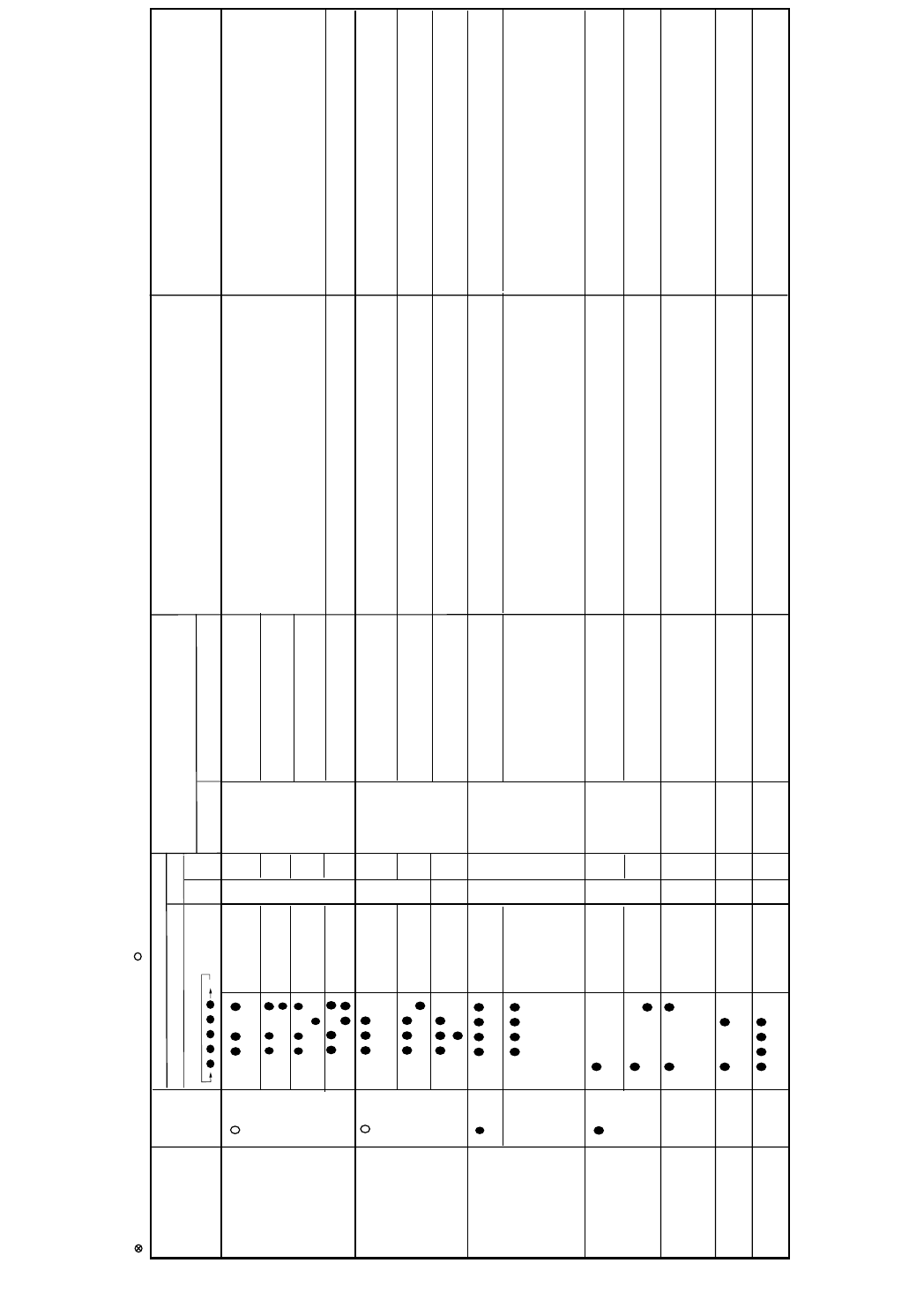
Status of
indoor
/
outdoor
units
Indication by
LE
D
1on
outdoor unit
*2
Indi
cation on i
n
door unit
Content of diagnosi
s
Inspection location/method
R
emedy
Floor / ceilin
g
W
a
ll
(Panel)
Lighting pattern at the time of timer l
a
mp
l
i
g
hting
Main
S
ub
for 5 seco
n
ds
M
ain category
Sub categor
y
Fla
s
h
es in 1-sec intervals (
n
ormal) : 1sec ON / 1s
e
cOF
F
X
:
:
OFF : Flash
es 3 ti
m
es in 0.2-
se
ci
nt
ervals
X
13 -0
-1
-2
14 -0
17 -0
-1
18 -0
19
-0
20 -0
30 -0
-1
Operation lamp(RED)
Cluster lamp(BLUE)
Operation lamp(RED)
Cluster lamp(BLUE)
Operation lamp(RED)
Cluster lamp(BLUE)
Operation lamp(RED)
Cluster lamp(BLUE)
Operation lamp(RED)
Cluster lamp(BLUE)
Operation lamp(RED)
Cluster lamp(BLUE)
Operation lamp(RED)
Cluster lamp(BLUE)
Operation lamp(RED)
Cluster lamp(BLUE)
Operation lamp(RED)
Cluster lamp(BLUE)
Operation lamp(RED)
Cluster lamp(BLUE)
Operation lamp(RED)
Cluster lamp(BLUE)
Operation lamp(RED)
Cluster lamp(BLUE)
Operation lamp(RED)
Cluster lamp(BLUE)
Indoor/outdoor units in
complete shutdown
Indoor/outdoor units in
complete shutdown
Indoor/outdoor units in
complete shutdown
DC compressor
Compressor startup error
(1)Check the colors (red,white,orange)of the compressor cords for proper
connection. (PWB side, compressor side)
(2)Check if the IPM terminal resistance values are uniform.
(3)Check if outdoor main relay (MRY1) turns on and voltage of both end of
the condenser (C10) has become DC380V.
(4)No abnormality found in above inspections(1)and(3).
(5)No abnormality found in above inspections(1)and(4).
(1)Correct the installation. (U:Red,V:White,W:Orange)
(2)Replace the outdoor unit control PWB assembl
y.
(3)Replace the outdoor unit control PWB assembl
y.
(4)Replace the outdoor unit control PWB assembl
y.
(5)Replace the compressor.
Compressor rotation error.
(at 120º energizing)
Compressor rotation error
(at 180º energizing)
Detection error of inverter current.
Outdoor unit
Active Filter
Active Filter overvoltage error
(1)Check the AC power supply voltage for fluc
tuation.
(2)No abnormality found in above inspec
tion (1).
(3)Replace the Active Filter.
(1)Connect stable power supply.
(2)Replace the outdoor unit control PCB assembly.
Clock error
(1)Check the clock for proper
inputt.
(1)Replace the outdoor unit control PCB assembly.
Indoor unit in operation
Outdoor unit in
complete shutdown
Indoor unit in operation
Outdoor unit in
complete shutdown
Indoor/outdoor units in
operation
Indoor/outdoor units in
operation
Wires between
units
Serial open-circuit
(1)Check the wires between units.
(2)Check voltage between N and 1 the indoor/outdoor unit terminal boards.
(1)Connect stable power supply.
(2)Replace the outdoor unit control PCB assembly.
(1)Check the wires between units.
(2)Check the outdoor unit fuse.
(3)Check 15-V,13-V and 5-V voltages on the PCB.
Check resistance between IPM terminals.
(4)Check pins No.5 and 8 of connector CN3 o
f the outdoor
unit fan motor
for short-circuit.
(5)Outdoor unit control PCB.
(1)Correct the wiring.
(2)Replace the fuse/outdoor unit control PCB assembly.
(3)Replace the outdoor unit control PCB assembly.
(4)Replace the outdoor unit fan motor.
(5)Replace the outdoor unit control PCB board.
Wires between
units
Serial short-circuit
(1)Check the wires between units. (1)Correct the wiring.
Serial erroneous wiring
(1)Check the wires between units.
(1)Correct the wiring.
Indoor unit fan
Indoor unit fan error (1)Check the indoor fan motor for proper rotating operation. (Check fan lock.)
(2)Check the lead wire of the indoor fan motor for open-circuit.
(3)Check connector of the indoor unit fan motor for secure installation.
(4)No abnormality found in above inspections (1)through (3).
(1)Replace the indoor fan motor.
(2)Replace the indoor fan motor.
(3)Correct the installation of CN3 of the indoor fan motor.
(4)Replace the indoor unit control PCB.
Indoor unit
control PCB
EEPROM data error (EEPROM read data error)
(1)Replace the indoor unit control PCB.
Drainpumpunit
Drain pump unit error
(1)Check connector CN2 and CN10.
(1)Replace the Drain pump unit unit.
(2)Re-insertion of CN2 and CN10.
13 time
14 time
X
X
X
X
Erroneous wiring
Operation lamp(RED)
Cluster lamp(BLUE)
-4
low valtage error
(1)Check the AC power supply valtage for fluntuation.
(1)Conect stable power supply.
(2)Replace tfe outdoor unit control PCB assembl
y.
3
-
(1)Check the circuit of detection of inverter current.
(1)Replace the outdoor unit control PCB assembl
y.